From Surf Wiki (app.surf) — the open knowledge base
Wire-frame model
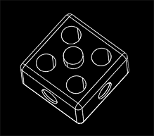
Representation of a 3D object with only its edges rendered

Representation of a 3D object with only its edges rendered
the 3D visualization

In 3D computer graphics, a wire-frame model (also spelled wireframe model) is a visual representation of a three-dimensional (3D) physical object. It is based on a polygon mesh or a volumetric mesh, created by specifying each edge of the physical object where two mathematically continuous smooth surfaces meet, or by connecting an object's constituent vertices using (straight) lines or curves.
The object is projected into screen space and rendered by drawing lines at the location of each edge. The term "wire frame" comes from designers using metal wire to represent the three-dimensional shape of solid objects. 3D wireframe computer models allow for the construction and manipulation of solids and solid surfaces. 3D solid modeling efficiently draws higher quality representations of solids than conventional line drawing.
Using a wire-frame model allows for the visualization of the underlying design structure of a 3D model. Traditional two-dimensional views and drawings/renderings can be created by the appropriate rotation of the object, and the selection of hidden-line removal via cutting planes.
Since wire-frame renderings are relatively simple and fast to calculate, they are often used in cases where a relatively high screen frame rate is needed (for instance, when working with a particularly complex 3D model, or in real-time systems that model exterior phenomena).
When greater graphical detail is desired, surface textures can be added automatically after the completion of the initial rendering of the wire frame. This allows a designer to quickly review solids, or rotate objects to different views without the long delays associated with more realistic rendering, or even the processing of faces and simple flat shading.
The wire frame format is also well-suited and widely used in programming tool paths for direct numerical control (DNC) machine tools.
Hand-drawn wire-frame-like illustrations date back as far as the Italian Renaissance. Wire-frame models were also used extensively in video games to represent 3D objects during the 1980s and early 1990s, when "properly" filled 3D objects would have been too complex to calculate and draw with the computers of the time. Wire-frame models are also used as the input for computer-aided manufacturing (CAM).
There are three main types of 3D computer-aided design (CAD) models; wire frame is the most abstract and least realistic. The other types are surface and solid. The wire-frame method of modelling consists of only lines and curves that connect the points or vertices and thereby define the edges of an object.
Simple example of wireframe model
An object is specified by two tables: (1) Vertex Table, and, (2) Edge Table.
The vertex table consists of three-dimensional coordinate values for each vertex with reference to the origin.
| Vertex | X | Y | Z |
|---|---|---|---|
| 1 | 1 | 1 | 1 |
| 2 | 1 | -1 | 1 |
| 3 | -1 | -1 | 1 |
| 4 | -1 | 1 | 1 |
| 5 | 1 | 1 | -1 |
| 6 | 1 | -1 | -1 |
| 7 | -1 | -1 | -1 |
| 8 | -1 | 1 | -1 |
Edge table specifies the start and end vertices for each edge.
| Edge | Start Vertex | End Vertex |
|---|---|---|
| 1 | 1 | 2 |
| 2 | 2 | 3 |
| 3 | 3 | 4 |
| 4 | 4 | 1 |
| 5 | 5 | 6 |
| 6 | 6 | 7 |
| 7 | 7 | 8 |
| 8 | 8 | 5 |
| 9 | 1 | 5 |
| 10 | 2 | 6 |
| 11 | 3 | 7 |
| 12 | 4 | 8 |
A naive interpretation could create a wire-frame representation by simply drawing straight lines between the screen coordinates of the appropriate vertices using the edge list.
Unlike representations designed for more detailed rendering, face information is not specified (it must be calculated if required for solid rendering).
Appropriate calculations have to be performed to transform the 3D coordinates of the vertices into 2D screen coordinates.
Technical communication explosions

Special CAD software is normally used for this very specialized work and is often available through major CAD software developers. In recent years, however, many new programs for this work are available through smaller developers who specialize in CAD rendering tools.
References
References
- Nasifoglu, Yelda. (7 November 2012). "Renaissance wireframe". McGill University.
This article was imported from Wikipedia and is available under the Creative Commons Attribution-ShareAlike 4.0 License. Content has been adapted to SurfDoc format. Original contributors can be found on the article history page.
Ask Mako anything about Wire-frame model — get instant answers, deeper analysis, and related topics.
Research with MakoFree with your Surf account
Create a free account to save articles, ask Mako questions, and organize your research.
Sign up freeThis content may have been generated or modified by AI. CloudSurf Software LLC is not responsible for the accuracy, completeness, or reliability of AI-generated content. Always verify important information from primary sources.
Report