From Surf Wiki (app.surf) — the open knowledge base
Unijunction transistor
Type of transistor
Type of transistor
| Field | Value | ||
|---|---|---|---|
| name | Unijunction Transistor | ||
| image | Image:unijunction transistors.jpg | ||
| image_size | 110px | ||
| caption | Unijunction transistors | ||
| type | active | ||
| invented | General Electric (1953) | ||
| symbol | [[File:IEEE 315-1975 (1993) 8.6.8.svg | 100px]] [[File:IEEE 315-1975 (1993) 8.6.9.svg | 100px]] |
| UJT N and P symbol | |||
| pins | B2, B1, emitter |
UJT N and P symbol A unijunction transistor (UJT) is a three-lead electronic semiconductor device with only one junction. It acts exclusively as an electrically controlled switch.
The UJT is not used as a linear amplifier. It is used in free-running oscillators, synchronized or triggered oscillators, and pulse generation circuits at low to moderate frequencies (hundreds of kilohertz). It is widely used in the triggering circuits for silicon controlled rectifiers. In the 1960s, the low cost per unit, combined with its unique characteristic, warranted its use in a wide variety of applications like oscillators, pulse generators, saw-tooth generators, triggering circuits, phase control, timing circuits, and voltage- or current-regulated supplies. The original unijunction transistor types are now considered obsolete, but a later multi-layer device, the programmable unijunction transistor, is still widely available.
Types
There are three types of unijunction transistor:
- The original unijunction transistor, or UJT, is a simple device that is essentially a bar of n-type semiconductor material into which p-type material has been diffused somewhere along its length, fixing the device parameter \eta (the "intrinsic stand-off ratio"). The 2N2646 model is the most commonly used version of the UJT.
- The complementary unijunction transistor, or CUJT, is a bar of p-type semiconductor material into which n-type material has been diffused somewhere along its length, defining the device parameter \eta. The 2N6114 model is one version of the CUJT.
- The programmable unijunction transistor, or PUT, is a multi-junction device that, with two external resistors, displays similar characteristics to the UJT. It is a close cousin to the thyristor and like the thyristor consists of four p-n layers. It has an anode and a cathode connected to the first and the last layer respectively, and a gate connected to one of the inner layers. PUTs are not directly interchangeable with conventional UJTs but perform a similar function. In a proper circuit configuration with two "programming" resistors for setting the parameter \eta, they behave like a conventional UJT. The 2N6027, 2N6028 and BRY39 models are examples of such devices.
Applications
Unijunction transistor circuits were popular in hobbyist electronics circuits in the 1960s and 1970s because they allowed simple oscillators to be built using just one active device. For example, they were used for relaxation oscillators in variable-rate strobe lights. Later, as integrated circuits became more popular, oscillators such as the 555 timer IC became more commonly used.
In addition to its use as the active device in relaxation oscillators, one of the most important applications of UJTs or PUTs is to trigger thyristors (silicon controlled rectifiers (SCR), TRIACs, etc.). A DC voltage can be used to control a UJT or PUT circuit such that the "on-period" increases with an increase in the DC control voltage. This application is important for large AC current control.
UJTs can also be used to measure magnetic flux. The Hall effect modulates the voltage at the PN junction. This affects the frequency of UJT relaxation oscillators.{{cite journal
Construction

The UJT has three terminals: an emitter (E) and two bases (B1 and B2) and so is sometimes known a "double-base diode". The base is formed by a lightly doped n-type bar of silicon. Two ohmic contacts B1 and B2 are attached at its ends. The emitter is of heavily-doped p-type material. The single PN junction between the emitter and the base gives the device its name. The resistance between B1 and B2 when the emitter is open-circuit is called interbase resistance. The emitter junction is usually located closer to base-2 (B2) than base-1 (B1) so that the device is not symmetrical, because a symmetrical unit does not provide optimum electrical characteristics for most of the applications.
If no potential difference exists between its emitter and either of its base leads, there is an extremely small current from B1 to B2. On the other hand, if an adequately large voltage relative to its base leads, known as the trigger voltage, is applied to its emitter, then a very large current from its emitter joins the current from B1 to B2, which creates a larger B2 output current.
The schematic diagram symbol for a unijunction transistor represents the emitter lead with an arrow, showing the direction of conventional current when the emitter-base junction is conducting a current. A complementary UJT uses a p-type base and an n-type emitter, and operates the same as the n-type base device but with all voltage polarities reversed.
The structure of a UJT is similar to that of an N-channel JFET, but p-type (gate) material surrounds the N-type (channel) material in a JFET, and the gate surface is larger than the emitter junction of UJT. A UJT is operated with the emitter junction forward-biased while the JFET is normally operated with the gate junction reverse-biased. The UJT is a current-controlled negative resistance device.
Device operation
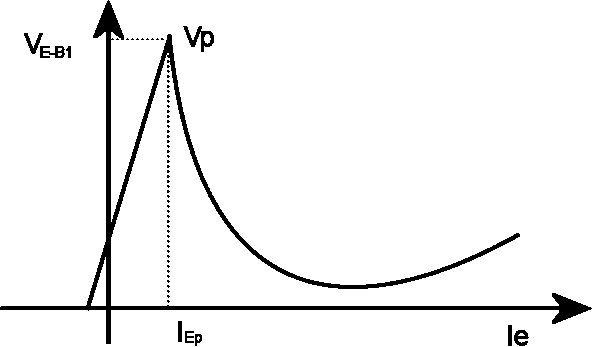
The device has a unique characteristic in that when it is triggered, its emitter current increases regeneratively until it is restricted by the emitter power supply. It exhibits a negative resistance characteristic and so it can be employed as an oscillator.
The UJT is biased with a positive voltage between the two bases. This causes a potential drop along the length of the device. When the emitter voltage is driven approximately one diode voltage above the voltage at the point where the P diffusion (emitter) is, current will begin to flow from the emitter into the base region. Because the base region is very lightly doped, the additional current (actually charges in the base region) causes conductivity modulation, which reduces the resistance of the portion of the base between the emitter junction and the B2 terminal. This reduction in resistance means that the emitter junction is more forward biased, and so even more current is injected. Overall, the effect is a negative resistance at the emitter terminal. This is what makes the UJT useful, especially in simple oscillator circuits.
Invention
The unijunction transistor was invented as a byproduct of research on germanium tetrode transistors at General Electric. It was patented in 1953. Commercially, silicon devices were manufactured. A common part number is 2N2646.
References
References
- https://saliterman.umn.edu/sites/saliterman.dl.umn.edu/files/general/solid_state_power_switching.pdf Page 12
- J. F. Cleary (ed.), ''General Electric Transistor Manual'', General Electric, 1964 Chapter 13 "Unijunction Transistor Circuits"
- 2N6027, 2N6028 data sheet by ON Semiconductor, at [http://www.farnell.com/datasheets/112532.pdf farnell.com]
- Jack Ward. (2005). "Transistor Museum Oral History Suran Index GE Unijunction Transistors". SemiconductorMuseum.com.
- "General Electric History - Transistor History". Google.com.
This article was imported from Wikipedia and is available under the Creative Commons Attribution-ShareAlike 4.0 License. Content has been adapted to SurfDoc format. Original contributors can be found on the article history page.
Ask Mako anything about Unijunction transistor — get instant answers, deeper analysis, and related topics.
Research with MakoFree with your Surf account
Create a free account to save articles, ask Mako questions, and organize your research.
Sign up freeThis content may have been generated or modified by AI. CloudSurf Software LLC is not responsible for the accuracy, completeness, or reliability of AI-generated content. Always verify important information from primary sources.
Report