From Surf Wiki (app.surf) — the open knowledge base
Tunnel crankcase
A tunnel crankcase, tunnel crankshaft or disc-webbed crankshaft{{Cite book
Tunnel crankcases appeared in the 1930s with the first high-speed diesel engines. They were favoured by some makers more than others, notably Saurer in Switzerland{{Cite book
Origins
With the development of the high-speed diesel engine around 1930, powerful diesel engines became available in the sizes previously used by lower-powered petrol engines. In particular, their high BMEP and high torque led to high forces on the crankshaft bearings. These forces were greater than could be sustained by the small whitemetal bearings used for petrol engines. Although aircraft and sports car engines in the 1920s developed to have considerable power in a small space, these were high maintenance machines with regular servicing. The new diesels were intended for long commercial service where maintenance was a key cost to be reduced.
The need for an improved bearing technology led to the adoption of roller bearings, rather than whitemetal. Although they might be considered esoteric today, ball and roller crankshaft bearings were already in use in the 1920s for such mundane engines as the Austin 7.
Roller bearings require one-piece races for both inner and outer bearing tracks. Although split races are possible, they are expensive and difficult to fit.Split-race roller bearings have been used for the centre big-end bearing in the connecting rod of some three-cylinder steam locomotives. As the crank axle is complex and also includes the wheels, it is impossible to fit roller bearings to the centre in any other way. Whitemetal bearings were much more common, but were a recognised weak point of some classes, such as the LNER A4 A simpler means of fitting roller bearings is to enlarge the diameter of the bearing, so that it becomes larger than the entire crankshaft web. Assembly is now done by putting the outer race of the bearing over the crankshaft axially from one end, rather than by assembling two pieces radially.
An early development was the semi-tunnel crankshaft. This used large ball or roller bearings of the tunnel style for their centre bearings, but the end bearings (carrying the load of pistons on only a single side) remained with a small diameter bearing of conventional style. This reduced the bearing cost, and also reduced the linear speed of these smaller bearings. This was important as it also reduced the speed of the crankcase oil seals alongside them.
Roller bearing crankshafts were favoured in central Europe: Germany, Switzerland and Czechoslovakia, owing to the local development and predominance of rolling-element bearings, in contrast to the improved metallurgy being developed for plain bearing materials in the English-speaking world.
Maybach petrol engines
Tunnel crankshafts were only rarely applied to petrol engines. The development of large powerful engines, outside the rarefied aerospace materials of aircraft engines, coincided with the development of practical lightweight diesel engines that tended to supplant petrol.
One market that remained with petrol was that of engines for airships, a market in which Maybach was predominant.{{Cite web |archive-url=https://web.archive.org/web/20160726124943/http://www.tiger-tank.com/secure/journal41.htm |archive-date=26 July 2016
Maybach diesel engines
After the war, Maybach applied its knowledge of compact, high-speed engines to diesel engines, for the emerging market in diesel railway locomotives. These engines contrasted with those from other makers by being particularly powerful, both by weight and by volume. This was especially the case for the length, as Maybach's engines used a compact V layout at a time when most makers were still building long single-bank inline engines. Maybach's name became particularly associated with the tunnel crankcase design and these engines are still the best-known uses of the tunnel crankshaft.{{Cite book |orig-year=1977
Built-up and one-piece cranks
The first tunnel crankshafts were built-up with webs bolted to the side of the main bearings, much as for a conventional crankshaft, only larger (see cross-section illustration of the Saurer engine). Examples of these were also built by John Fowler & Co. in England.{{cite book

A later development was to enlarge the main bearings sufficiently to be larger than the entire crank web. This now permitted the use of a one piece crankshaft
A tunnel crankshaft is considered to be a 'tunnel' if the outside diameter over the outer race of the installed bearings is larger than the maximum size of the webs. Early, or smaller, engines may have had crankshafts with bearing journalsThe 'journal' is the part of the shaft forming the bearing, the bearing races are a separate component that fits over this. smaller than this, but were still considered as such because they were larger when the bearings were fitted.
To avoid passing the entire crankshaft through the bearings, the bearing diameters were usually stepped in size, in a conical progression. Each bearing now only needed to be slid through the length of its own width, being small enough to pass easily through any preceding housings. This meant that the crankshaft could only be inserted from one end of the crankcase.
Advantages
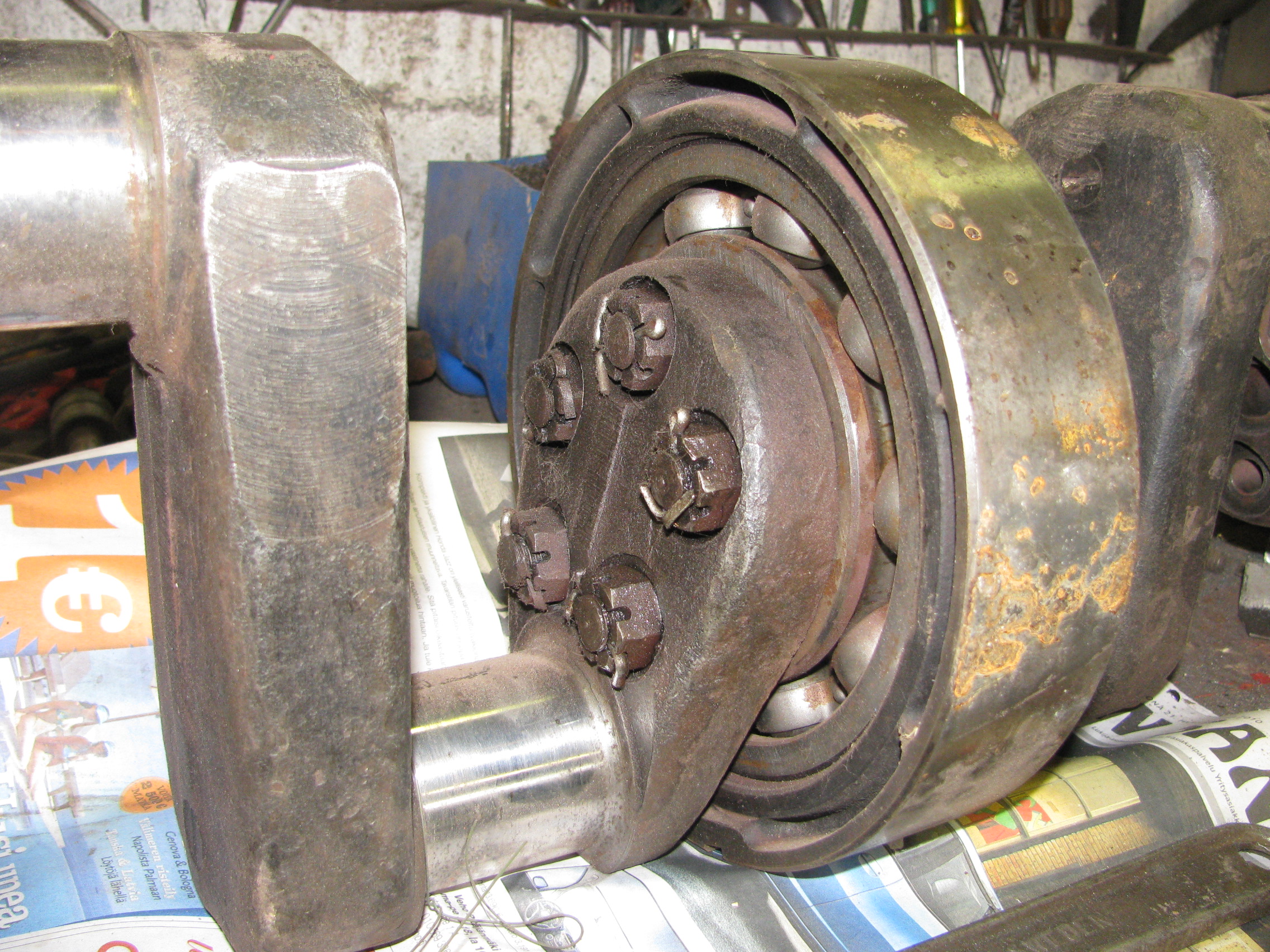
.jpg)
; Bearing diameter Larger bearings can support the loads of these higher-force engines.
; Use of roller bearings These can cope with the greater forces and higher speeds of the new high-speed engines.
; Assembly The crankshaft can be inserted into an assembled crankcase, rather than the bearing caps being assembled around it. This is usually done by rotating the crankcase end-upwards and then lowering the crankshaft vertically into it.
This was a noted feature of some 1960s Maybach engines, used for diesel locomotives.
; Reduced crankshaft length The length previously required for one (web + bearing + web) group is now replaced by a single bearing length, also acting as both webs.
As this reduced crankshaft length also reduces the spacing between cylinders, it was one factor in encouraging the use of tunnel crankshafts in V engines, where there is more axial distance available between adjacent cylinders. This further reduces the overall length of tunnel crankshaft engines.
; Increased crankshaft stiffness The crankshaft, particularly along the webs, becomes wider and so stiffer.
Disadvantages
; Increased linear bearing speed By simple geometry, as the bearing diameter increases, so too does the linear speed at the bearing surface. This exceeds that possible for whitemetal bearings. Roller bearings were thus not only one reason for the enlarged tunnel crankshaft, but they were also made necessary by it.
; Crankshaft manufacturing The diameter and mass of the crankshaft is increased, such that it will no longer fit into standard crankshaft grinding machines and may require specialised machinery for their manufacture. Although the reduced length of the crankshaft may allow large engines to be built with shorter machinery.
; Crankshaft inertia The enlarged webs have greater mass, thus greater rotational inertia, particularly as they place this mass at the greatest radius away from the axis of the crankshaft. This gives an engine that is slower to accelerate, although it also means that the engine maintains a constant speed more easily under a rapidly varying load.
For this reason, the tunnel crankshaft is most appropriate to engines running for long periods at constant speed, such as generator sets, railway locomotives and boats. They are not used for cars, where rapid acceleration and deceleration is needed.
; Crankcase rigidity The large amount of material removed from the crankcase to provide the tunnel does not allow as much space for stiffening webs across the crankcase, so the overall rigidity of the crankcase may be less.
Two-stroke engines

Many small crankcase compression two-stroke engines have a crankshaft with large circular webs,{{cite book
Some multi-cylinder two-stroke engines also use crankcase compression, almost all of them marine outboard motors. In these engines, the separate crankcase volume for each cylinder must be kept separate. The webs are thus made circular, large and sealed by gas seals on their outer circumference. Again, these are not considered as tunnel crankshafts if the webs only carry a seal, but may be so if the large web also forms the bearing.
References
References
- {{harvnb. Diesel Manual. 1963
- {{harvnb. Irving. 1967
This article was imported from Wikipedia and is available under the Creative Commons Attribution-ShareAlike 4.0 License. Content has been adapted to SurfDoc format. Original contributors can be found on the article history page.
Ask Mako anything about Tunnel crankcase — get instant answers, deeper analysis, and related topics.
Research with MakoFree with your Surf account
Create a free account to save articles, ask Mako questions, and organize your research.
Sign up freeThis content may have been generated or modified by AI. CloudSurf Software LLC is not responsible for the accuracy, completeness, or reliability of AI-generated content. Always verify important information from primary sources.
Report