From Surf Wiki (app.surf) — the open knowledge base
Tomography
Imaging by sections or sectioning using a penetrative wave
Imaging by sections or sectioning using a penetrative wave

Tomography is imaging by sections or sectioning that uses any kind of penetrating wave. The method is used in radiology, archaeology, biology, atmospheric science, geophysics, oceanography, plasma physics, materials science, cosmochemistry, astrophysics, quantum information, and other areas of science.
The word tomography is derived from Ancient Greek τόμος, and γράφω, or, in this context as well, . A device used in tomography is called a tomograph, while the image produced is a tomogram.
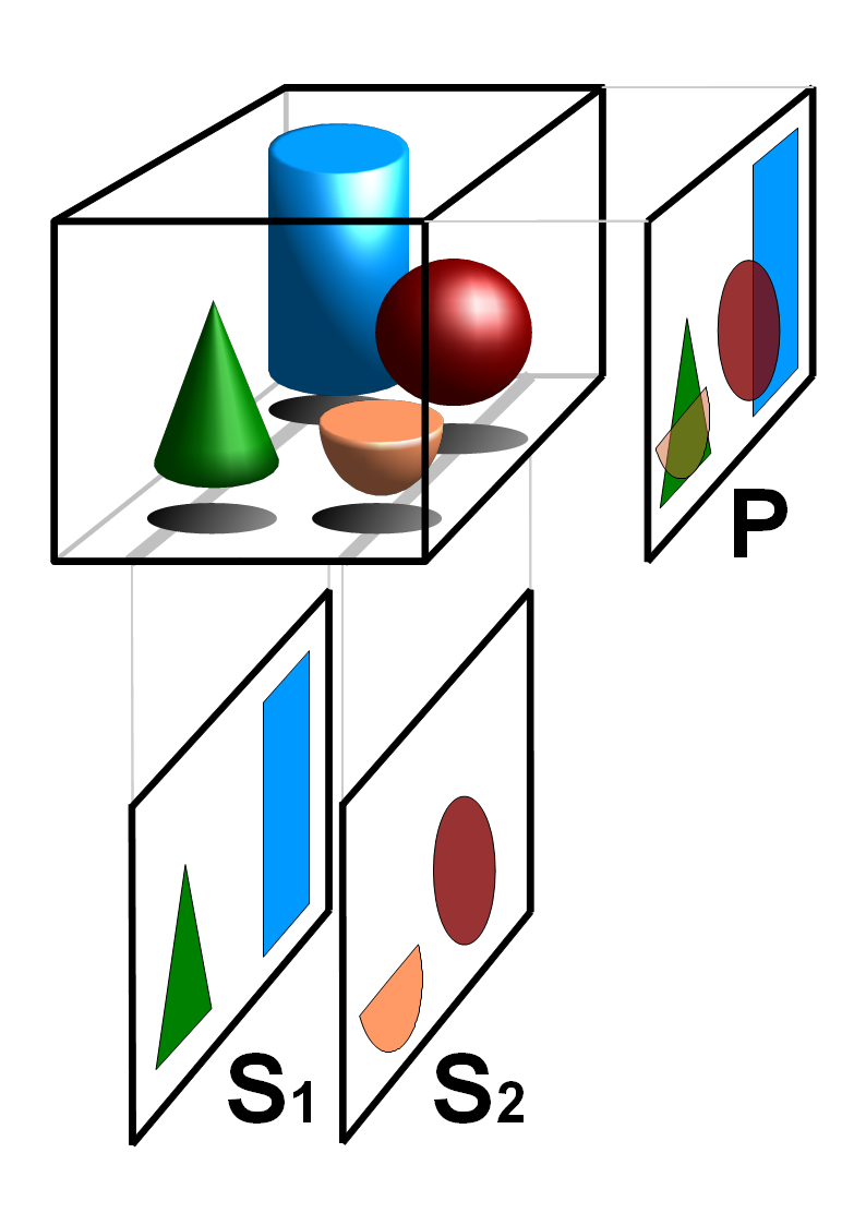
In many cases, the production of these images is based on the mathematical procedure tomographic reconstruction, such as X-ray computed tomography technically being produced from multiple projectional radiographs. Many different reconstruction algorithms exist. Most algorithms fall into one of two categories: filtered back projection (FBP) and iterative reconstruction (IR). These procedures give inexact results: they represent a compromise between accuracy and computation time required. FBP demands fewer computational resources, while IR generally produces fewer artifacts (errors in the reconstruction) at a higher computing cost.
Although MRI (magnetic resonance imaging), optical coherence tomography and ultrasound are transmission methods, they typically do not require movement of the transmitter to acquire data from different directions. In MRI, both projections and higher spatial harmonics are sampled by applying spatially varying magnetic fields; no moving parts are necessary to generate an image. On the other hand, since ultrasound and optical coherence tomography uses time-of-flight to spatially encode the received signal, it is not strictly a tomographic method and does not require multiple image acquisitions.
Types of tomography
| Name | Source of data | Abbreviation | Year of introduction |
|---|---|---|---|
| Aerial tomography | Electromagnetic radiation | AT | 2020 |
| Array tomography | Correlative light and electron microscopy | AT | 2007 |
| Atom probe tomography | Atom probe | APT | 1986 |
| Computed tomography imaging spectrometer | Visible light spectral imaging | CTIS | 2001 |
| Computed tomography of chemiluminescence | Chemiluminescence Flames | CTC | 2009 |
| Confocal microscopy (laser scanning confocal microscopy) | Laser scanning confocal microscopy | LSCM | |
| Cryogenic electron tomography | Cryogenic transmission electron microscopy | CryoET | |
| Electrical capacitance tomography | Electrical capacitance | ECT | 1988 |
| Electrical capacitance volume tomography | Electrical capacitance | ECVT | |
| Electrical resistivity tomography | Electrical resistivity | ERT | |
| Electrical impedance tomography | Electrical impedance | EIT | 1984 |
| Atomic Mineral Resonance Tomography | Atomic Mineral Resonance Frequency | AMRT | |
| Electron tomography | Transmission electron microscopy | ET | 1968 |
| Focal plane tomography | X-ray | 1930s | |
| Functional magnetic resonance imaging | Magnetic resonance | fMRI | 1992 |
| Gamma-ray emission tomography ("Tomographic Gamma Scanning") | Gamma ray | TGS or ECT | |
| Gamma-ray transmission tomography | Gamma ray | TCT | |
| Hydraulic tomography | fluid flow | HT | 2000 |
| Infrared microtomographic imaging | Mid-infrared | 2013 | |
| Laser Ablation Tomography | Laser ablation & fluorescent microscopy | LAT | 2013 |
| Magnetic induction tomography | Magnetic induction | MIT | |
| Magnetic particle imaging | Superparamagnetism | MPI | 2005 |
| Magnetic resonance imaging or nuclear magnetic resonance tomography | Nuclear magnetic moment | MRI or MRT | |
| Multi-source tomography | X-ray | ||
| Muon tomography | Muon | ||
| Microwave tomography | Microwave | ||
| Neutron tomography | Neutron | ||
| Neutron stimulated emission computed tomography | |||
| Ocean acoustic tomography | Sonar | OAT | |
| Optical coherence tomography | Interferometry | OCT | |
| Optical diffusion tomography | Absorption of light | ODT | |
| Optical projection tomography | Optical microscope | OPT | |
| Photoacoustic imaging in biomedicine | Photoacoustic spectroscopy | PAT | |
| Photoemission orbital tomography | Angle-resolved photoemission spectroscopy | POT | 2009 |
| Positron emission tomography | Positron emission | PET | |
| Positron emission tomography - computed tomography | Positron emission & X-ray | PET-CT | |
| Quantum tomography | Quantum state | QST | |
| Single-photon emission computed tomography | Gamma ray | SPECT | |
| Seismic tomography | Seismic waves | ||
| Terahertz tomography | Terahertz radiation | THz-CT | |
| Thermoacoustic imaging | Photoacoustic spectroscopy | TAT | |
| Ultrasound-modulated optical tomography | Ultrasound | UOT | |
| Ultrasound computer tomography | Ultrasound | USCT | |
| Ultrasound transmission tomography | Ultrasound | ||
| X-ray computed tomography | X-ray | CT, CAT scan | 1971 |
| X-ray microtomography | X-ray | microCT | |
| Zeeman-Doppler imaging | Zeeman effect |
Some recent advances rely on using simultaneously integrated physical phenomena, e.g. X-rays for both CT and angiography, combined CT/MRI and combined CT/PET.
Discrete tomography and Geometric tomography, on the other hand, are research areas that deal with the reconstruction of objects that are discrete (such as crystals) or homogeneous. They are concerned with reconstruction methods, and as such they are not restricted to any of the particular (experimental) tomography methods listed above.
Synchrotron X-ray tomographic microscopy
A new technique called synchrotron X-ray tomographic microscopy (SRXTM) allows for detailed three-dimensional scanning of fossils.
The construction of third-generation synchrotron sources combined with the tremendous improvement of detector technology, data storage and processing capabilities since the 1990s has led to a boost of high-end synchrotron tomography in materials research with a wide range of different applications, e.g. the visualization and quantitative analysis of differently absorbing phases, microporosities, cracks, precipitates or grains in a specimen. Synchrotron radiation is created by accelerating free particles in high vacuum. By the laws of electrodynamics this acceleration leads to the emission of electromagnetic radiation (Jackson, 1975). Linear particle acceleration is one possibility, but apart from the very high electric fields one would need it is more practical to hold the charged particles on a closed trajectory in order to obtain a source of continuous radiation. Magnetic fields are used to force the particles onto the desired orbit and prevent them from flying in a straight line. The radial acceleration associated with the change of direction then generates radiation.
Volume rendering
Main article: Volume rendering

Volume rendering is a set of techniques used to display a 2D projection of a 3D discretely sampled data set, typically a 3D scalar field. A typical 3D data set is a group of 2D slice images acquired, for example, by a CT, MRI, or MicroCT scanner. These are usually acquired in a regular pattern (e.g., one slice every millimeter) and usually have a regular number of image pixels in a regular pattern. This is an example of a regular volumetric grid, with each volume element, or voxel represented by a single value that is obtained by sampling the immediate area surrounding the voxel.
To render a 2D projection of the 3D data set, one first needs to define a camera in space relative to the volume. Also, one needs to define the opacity and color of every voxel. This is usually defined using an RGBA (for red, green, blue, alpha) transfer function that defines the RGBA value for every possible voxel value.
For example, a volume may be viewed by extracting isosurfaces (surfaces of equal values) from the volume and rendering them as polygonal meshes or by rendering the volume directly as a block of data. The marching cubes algorithm is a common technique for extracting an isosurface from volume data. Direct volume rendering is a computationally intensive task that may be performed in several ways.
History
Focal plane tomography was developed in the 1930s by the radiologist Alessandro Vallebona, and proved useful in reducing the problem of superimposition of structures in projectional radiography.
In a 1953 article in the medical journal Chest, B. Pollak of the Fort William Sanatorium described the use of planography, another term for tomography.{{cite journal |archive-url = https://archive.today/20130414135338/http://chestjournal.chestpubs.org/content/24/6/663.abstract |url-status = dead |archive-date = 2013-04-14 |access-date = July 10, 2011
Focal plane tomography remained the conventional form of tomography until being largely replaced by mainly computed tomography in the late 1970s. Focal plane tomography uses the fact that the focal plane appears sharper, while structures in other planes appear blurred. By moving an X-ray source and the film in opposite directions during the exposure, and modifying the direction and extent of the movement, operators can select different focal planes which contain the structures of interest.
References
References
- Herman, Gabor T.. (2009). "Fundamentals of Computerized Tomography: Image Reconstruction from Projections". Springer.
- (July 2007). "Array Tomography: A New Tool for Imaging the Molecular Architecture and Ultrastructure of Neural Circuits". Neuron.
- (February 2001). "Computed Tomography-Based Spectral Imaging For Fluorescence Microscopy". Biophysical Journal.
- (February 2011). "Computed Tomography of Chemiluminescence (CTC): Instantaneous 3D measurements and Phantom studies of a turbulent opposed jet flame". Combustion and Flame.
- (10 September 2017). "Instantaneous 3D imaging of highly turbulent flames using computed tomography of chemiluminescence.". Applied Optics.
- (1988). "Capacitance-based tomographic flow imaging system". Electronics Letters.
- (2015). "The ASTRA Toolbox: a platform for advanced algorithm development in electron tomography". Ultramicroscopy.
- (1970-06-23). "The reconstruction of a three-dimensional structure from projections and its application to electron microscopy". Proc. R. Soc. Lond. A.
- (2006). "Electron tomography: methods for three-dimensional visualization of structures in the cell". Springer.
- (September 2013). "3D spectral imaging with synchrotron Fourier transform infrared spectro-microtomography". Nature Methods.
- Cramer, A., Hecla, J., Wu, D. et al. Stationary Computed Tomography for Space and other Resource-constrained Environments. Sci Rep 8, 14195 (2018). [https://doi.org/10.1038/s41598-018-32505-z]
- V. B. Neculaes, P. M. Edic, M. Frontera, A. Caiafa, G. Wang and B. De Man, "Multisource X-Ray and CT: Lessons Learned and Future Outlook," in IEEE Access, vol. 2, pp. 1568–1585, 2014, doi: 10.1109/ACCESS.2014.2363949.[https://www.researchgate.net/publication/273170153_Multisource_X-Ray_and_CT_Lessons_Learned_and_Future_Outlook]
- (December 2015). "Three dimensions localization of tumors in confocal microwave imaging for breast cancer detection". Microwave and Optical Technology Letters.
- (30 October 2009). "Reconstruction of Molecular Orbital Densities from Photoemission Data". Science.
- (February 2016). "Fast and Flexible X-ray Tomography Using the ASTRA Toolbox". Optics Express.
- (10 August 2006). "Synchrotron X-ray tomographic microscopy of fossil embryos.". Nature.
- (2021). "Metals, Microbes, and Minerals - the Biogeochemical Side of Life". De Gruyter.
- Banhart, John, ed. Advanced Tomographic Methods in Materials Research and Engineering. Monographs on the Physics and Chemistry of Materials. Oxford; New York: Oxford University Press, 2008.
- Littleton, J.T.. "A History of the Radiological Sciences". [[American Roentgen Ray Society]].
This article was imported from Wikipedia and is available under the Creative Commons Attribution-ShareAlike 4.0 License. Content has been adapted to SurfDoc format. Original contributors can be found on the article history page.
Ask Mako anything about Tomography — get instant answers, deeper analysis, and related topics.
Research with MakoFree with your Surf account
Create a free account to save articles, ask Mako questions, and organize your research.
Sign up freeThis content may have been generated or modified by AI. CloudSurf Software LLC is not responsible for the accuracy, completeness, or reliability of AI-generated content. Always verify important information from primary sources.
Report