From Surf Wiki (app.surf) — the open knowledge base
Six-bar linkage
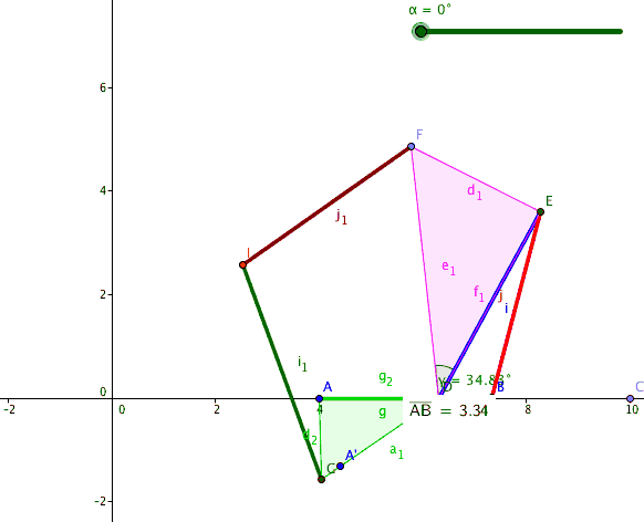
1-DoF mechanism with 6 links and 7 joints

1-DoF mechanism with 6 links and 7 joints
In mechanics, a six-bar linkage is a mechanism with one degree of freedom that is constructed from six links and seven joints. An example is the Klann linkage used to drive the legs of a walking machine.
In general, each joint of a linkage connects two links, and a binary link supports two joints. If we consider a hexagon constructed from six binary links with six of the seven joints forming its vertices, then the seventh joint can be added to connect two sides of the hexagon to form a six-bar linkage with two ternary links connected by one joint. This type of six-bar linkage is said to have the Watt topology.
A six-bar linkage can also be constructed by first assembling five binary links into a pentagon, which uses five of the seven joints, and then completing the linkage by adding a binary link that connects two sides of the pentagon. This again creates two ternary links that are now separated by one or more binary links. This type of six-bar linkage is said to have the Stephenson topology.
The Klann linkage has the Stephenson topology.
Watt six-bar linkage
Watt's parallel motion generator consists of the four-bar linkage that has a coupler curve that traces an approximately straight line trajectory, combined with a parallelogram linkage that copies this straight line movement to a desired location. This configuration of six bars and seven joints has two four-bar loops.
Stephenson six-bar linkage
The six-bars and seven joints of the Stephenson linkage comprise one four-bar loop and one five-bar loop. It has two ternary links that are separated by a binary link. This means the two ternary links are not connected to each other by a joint as in the case of the Watt topology.
The Stephenson has three forms depending on the link that is selected as the frame, which are denoted Stephenson I, II and III.
References
References
- [https://books.google.com/books?id=jv9mQyjRIw4C&q=geometric+design+of+linkages J. M. McCarthy and G. S. Soh, '''Geometric Design of Linkages,''' 2nd Edition, Springer 2010]
- An animation of [https://www.youtube.com/watch?v=TS3m8ChRb4k a six-bar linkage with the Watt topology.]
This article was imported from Wikipedia and is available under the Creative Commons Attribution-ShareAlike 4.0 License. Content has been adapted to SurfDoc format. Original contributors can be found on the article history page.
Ask Mako anything about Six-bar linkage — get instant answers, deeper analysis, and related topics.
Research with MakoFree with your Surf account
Create a free account to save articles, ask Mako questions, and organize your research.
Sign up freeThis content may have been generated or modified by AI. CloudSurf Software LLC is not responsible for the accuracy, completeness, or reliability of AI-generated content. Always verify important information from primary sources.
Report