From Surf Wiki (app.surf) — the open knowledge base
Runway
Surface used for takeoff or landing

Surface used for takeoff or landing
,_Netherlands_PP1151411211.jpg)
In aviation, a runway is an elongated, rectangular surface designed for the landing and takeoff of an aircraft. Runways may be a human-made surface (often asphalt, concrete, or a mixture of both) or a natural surface (grass, dirt, gravel, ice, sand or salt). Runways, taxiways and ramps, are sometimes referred to as "tarmac", though very few runways are built using tarmac. Takeoff and landing areas defined on the surface of water for seaplanes are generally referred to as waterways. Runway lengths are now commonly given in meters worldwide, except in North America where feet are commonly used.
History
In January 1919, aviation pioneer Orville Wright underlined the need for "distinctly marked and carefully prepared landing places, [but] the preparing of the surface of reasonably flat ground [is] an expensive undertaking [and] there would also be a continuous expense for the upkeep."
In 1919, based on WWI experience, the United States Army Air Service published Specifications for Municipal Landing Fields. It specified an 1800 by 1800 foot square with a central 150 foot takeoff runway in the shape of a cross. Through the 1930s though, most army planes landed in any direction, subject to the prevailing winds, on circular groomed and drained turf called "all-over fields." However, tire pressures were limited to less than seventy psi in such fields. After 1935, tire pressures exceeded that limit with increased aircraft size. According to Conway, "Confronted with snow and ice removal in the north, water nearly everywhere, and the demands placed by airlines on regularity, safety, and efficient transshipment of passengers and mail, the technology of the all-over turf field became obsolete in the United States during the 1920s." In 1928, Ford Airfield became the first U.S. airport to have concrete runways, and by 1932, all major U.S. airports had runways..."
Design
Orientation
The primary consideration in determining runway orientation is the prevailing wind direction, in lieu of spatial constraints or obstructions that may prevent optimal alignment. To mitigate the occurrence of crosswind operations which are more challenging and dangerous, runways at airports are designed to align with the wind's direction. Utilizing runways oriented with the wind direction also allows for aircraft to take-off and land into the headwind, reducing the length of runway used during operations. Taking off and landing into the wind increases the relative air speed of the aircraft to create more lift; this allows aircraft to reach take-off velocity with a shorter amount of ground roll and also allows aircraft to land with a slower ground speed. To determine the prevailing wind directions, analysis of a wind rose is used before constructing airport runways.
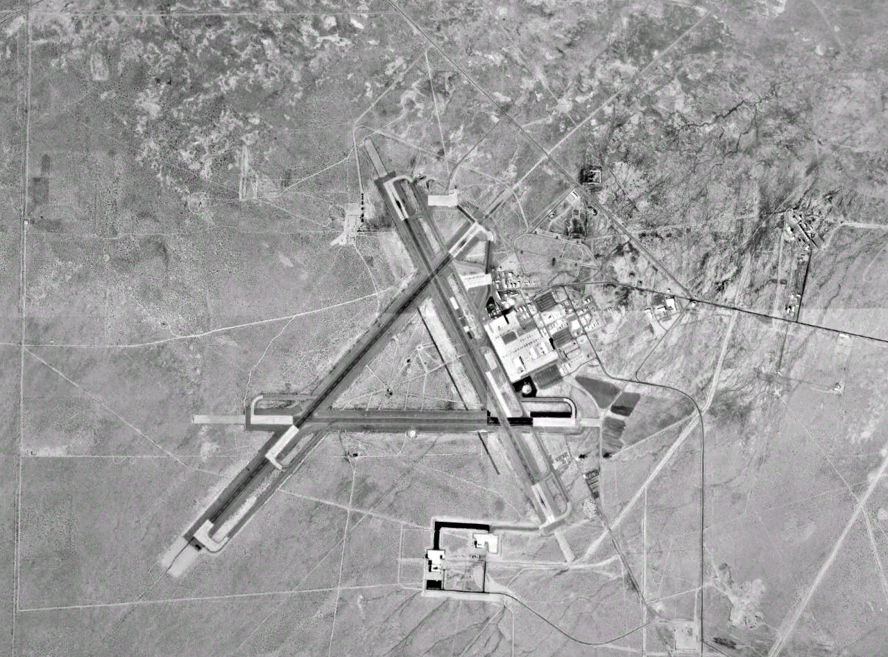
Originally in the 1920s and 1930s, airports and air bases (particularly in the United Kingdom) were built in a triangle-like pattern of three runways at 60° angles to each other. The reason was that aviation was only starting, and although it was known that wind affected the runway distance required, not much was known about wind behaviour. As a result, three runways in a triangle-like pattern were built, and the runway with the heaviest traffic would eventually expand into the airport's main runway, while the other two runways would be either abandoned or converted into taxiways.
Naming


Runways are named by a number between 01 and 36, which is generally the magnetic azimuth of the runway's heading in decadegrees. This heading differs from true north by the local magnetic declination. A runway numbered 09 points east (90°), runway 18 is south (180°), runway 27 points west (270°) and runway 36 points to the north (360° rather than 0°). When taking off from or landing on runway 09, a plane is heading around 90° (east). A runway can normally be used in both directions, and is named for each direction separately: e.g., "runway 15" in one direction is "runway 33" when used in the other. The two numbers differ by 18 (= 180°). For clarity in radio communications, each digit in the runway name is pronounced individually: runway one-five, runway three-three, etc. (instead of "fifteen" or "thirty-three").

A leading zero, for example in "runway zero-six" or "runway zero-one-left", is included for all ICAO and some U.S. military airports (such as Edwards Air Force Base). However, most U.S. civil aviation airports drop the leading zero as required by FAA regulation. This also includes some military airfields such as Cairns Army Airfield. This American anomaly may lead to inconsistencies in conversations between American pilots and controllers in other countries.
Military airbases may include smaller paved runways known as "assault strips" for practice and training next to larger primary runways. These strips eschew the standard numerical naming convention and instead employ the runway's full three digit heading; examples include Dobbins Air Reserve Base's Runway 110/290 and Duke Field's Runway 180/360.
Runways with non-hard surfaces, such as small turf airfields and waterways for seaplanes, may use the standard numerical scheme or may use traditional compass point naming, examples include Ketchikan Harbor Seaplane Base's Waterway E/W.{{cite web|title=Ketchikan Harbor Seaplane Base
Letter suffix

If there is more than one runway pointing in the same direction (parallel runways), each runway is identified by appending left (L), center (C) and right (R) to the end of the runway number to identify its position (when facing its direction)—for example, runways one-five-left (15L), one-five-center (15C), and one-five-right (15R). Runway zero-three-left (03L) becomes runway two-one-right (21R) when used in the opposite direction (derived from adding 18 to the original number for the 180° difference when approaching from the opposite direction). In some countries, regulations mandate that where parallel runways are too close to each other, only one may be used at a time under certain conditions (usually adverse weather).
At large airports with four or more parallel runways (for example, at Chicago O'Hare, Los Angeles, Detroit Metropolitan Wayne County, Hartsfield-Jackson Atlanta, Denver, Dallas–Fort Worth and Orlando), some runway identifiers are shifted by 1 to avoid the ambiguity that would result with more than three parallel runways. For example, in Los Angeles, this system results in runways 6L, 6R, 7L, and 7R, even though all four runways are actually parallel at approximately 69°. At Dallas/Fort Worth International Airport, there are five parallel runways, named 17L, 17C, 17R, 18L, and 18R, all oriented at a heading of 175.4°. Occasionally, an airport with only three parallel runways may use different runway identifiers, such as when a third parallel runway was opened at Phoenix Sky Harbor International Airport in 2000 to the south of existing 8R/26L—rather than confusingly becoming the "new" 8R/26L it was instead designated 7R/25L, with the former 8R/26L becoming 7L/25R and 8L/26R becoming 8/26.
Suffixes may also be used to denote special-use runways. Airports that have seaplane waterways may choose to denote the waterway on charts with the suffix W; such as Daniel K. Inouye International Airport in Honolulu and Lake Hood Seaplane Base in Anchorage. Small airports that host various forms of air traffic may employ additional suffixes to denote special runway types based on the type of aircraft expected to use them, including STOL aircraft (S), gliders (G), rotorcraft (H), and ultralights (U). Runways that are numbered relative to true north rather than magnetic north will use the suffix T; this is advantageous for certain airfields in the far north such as Thule Air Base (08T/26T).
Renumbering
Runway designations may be changed over time as the Earth's magnetic field shifts and their headings shift with it. This is more common at higher latitudes: for example, Fairbanks International Airport in Alaska renames runways roughly every 24 years, most recently in 2009. In northern Canada, runways are designated based on true north, which avoids the need to update them. Nav Canada, Canada's air navigation service provider, has advocated for an industry-wide switch to true north.
As runways are designated with headings rounded to the nearest 10°, some runways are affected sooner than others; e.g. a hypothetical Runway 23 with a heading of 226° would only have to shift to 224° to become Runway 22. Because magnetic drift itself is slow, these changes are uncommon, and not welcomed, as they require accompanying changes in aeronautical charts and descriptive documents. When a runway designation does change, it is often done at night, especially at major airports, because taxiway signs need to be changed and the numbers at each end of the runway need to be repainted to the new runway designators. In 2009 for example, London Stansted Airport in the United Kingdom changed its runway designation from 05/23 to 04/22 during the night.
Declared distances

Runway dimensions vary from as small as 245 m long and 8 m wide in smaller general aviation airports, to 5500 m long and 80 m wide at large international airports built to accommodate the largest jets, to the huge 11917 x lake bed runway 17/35 at Edwards Air Force Base in California – developed as a landing site for the Space Shuttle.
Takeoff and landing distances available are given using one of the following terms:
- Takeoff Run Available Takeoff Run Available (TORA) – The length of runway declared available and suitable for the ground run of an airplane taking off.
- Clearway Takeoff Distance Available (TODA) – The length of the takeoff run available plus the length of the clearway, if clearway is provided. (The clearway length allowed must lie within the aerodrome or airport boundary. According to the Federal Aviation Regulations and Joint Aviation Requirements (JAR) TODA is the lesser of TORA plus clearway or 1.5 times TORA).
- Stopway Accelerate-Stop Distance Available (ASDA)– The length of the takeoff run available plus the length of the stopway, if stopway is provided.
- Landing Distance Available Landing Distance Available (LDA) – The length of runway that is declared available and suitable for the ground run of an airplane landing.
- Emergency Distance Available Emergency Distance Available (EMDA) – LDA (or TORA) plus a stopway.
Sections
There are standards for runway markings.
- The runway thresholds are markings across the runway that denote the beginning and end of the designated space for landing and takeoff under non-emergency conditions.
- The runway safety area is the cleared, smoothed and graded area around the paved runway. It is kept free from any obstacles that might impede flight or ground roll of aircraft.
- The runway is the surface from threshold to threshold (including displaced thresholds), which typically features threshold markings, numbers, and centerlines, but excludes blast pads and stopways at both ends.blastpad
- Blast pads are often constructed just before the start of a runway where jet blast produced by large planes during the takeoff roll could otherwise erode the ground and eventually damage the runway.
- Stopways, also known as overrun areas, are also constructed at the end of runways as emergency space to stop planes that overrun the runway on landing or a rejected takeoff.
- Blast pads and stopways look similar, and are both marked with yellow chevrons; stopways may optionally be surrounded by red runway lights. The differences are that stopways can support the full weight of an aircraft and are designated for use in an aborted takeoff, while blast pads are often not as strong as the main paved surface of the runway and are not to be used for taxiing, landing, or aborted takeoffs. An engineered materials arrestor system (EMAS) may also be present, which may overlap with the end of the blast pad or stopway and is painted similarly (although an EMAS does not count as part of a stopway).
- Displaced thresholds may be used for taxiing, takeoff, and landing rollout, but not for touchdown. A displaced threshold often exists because of obstacles just before the runway, runway strength, or noise restrictions making the beginning section of runway unsuitable for landings. It is marked with white paint arrows that lead up to the beginning of the landing portion of the runway. As with blast pads, landings on displaced thresholds are not permitted aside from emergency use or exigent circumstance.
- Relocated thresholds are similar to displaced thresholds. They are used to mark a portion of the runway temporarily closed due to construction or runway maintenance. This closed portion of the runway is not available for use by aircraft for takeoff or landing, but it is available for taxi. While methods for identifying the relocated threshold vary, a common way for the relocated threshold to be marked is a ten-foot-wide white bar across the width of the runway.
- Clearway is an area beyond the paved runway, aligned with the runway centerline and under the control of the airport authorities. This area is not less than 500 ft and there are no protruding obstacles except for threshold lights provided they are not higher than 26 inches. There is a limit on the upslope of the clearway of 1.25%. The length of the clearway may be included in the length of the takeoff distance available. For example, if a paved runway is 2000 m long and there are 400 m of clearway beyond the end of the runway, the takeoff distance available is 2400 m long. When the runway is to be used for takeoff of a large airplane, the maximum permissible takeoff weight of the airplane can be based on the takeoff distance available, including clearway. Clearway allows large airplanes to take off at a heavier weight than would be allowed if only the length of the paved runway is taken into account.
Markings
There are runway markings and signs on most large runways. Larger runways have a distance remaining sign (black box with white numbers). This sign uses a single number to indicate the remaining distance of the runway in thousands of feet. For example, a 7 will indicate 7000 ft remaining. The runway threshold is marked by a line of green lights.
![Runway Identifying numbers being painted at Rocky Mountain Metropolitan Airport [KBJC]](https://upload.wikimedia.org/wikipedia/commons/0/0a/Runway_Number_Painting.jpg)
There are three types of runways:
- Visual runways are used at small airstrips and are usually just a strip of grass, gravel, ice, asphalt, or concrete. Although there are usually no markings on a visual runway, they may have threshold markings, designators, and centerlines. Additionally, they do not provide an instrument-based landing procedure; pilots must be able to see the runway to use it. Also, radio communication may not be available and pilots must be self-reliant.
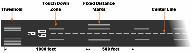
- Non-precision instrument runways are often used at small- to medium-size airports. These runways, depending on the surface, may be marked with threshold markings, designators, centerlines, and sometimes a 1000 ft mark (known as an aiming point, sometimes installed at 1500 ft). While centerlines provide horizontal position guidance, aiming point markers provide vertical position guidance to planes on visual approach.
- Precision instrument runways, which are found at medium- and large-size airports, consist of a blast pad/stopway (optional, for airports handling jets), threshold, designator, centerline, aiming point, and 500 ft, 1000 ft/1500 ft, 2000 ft, 2500 ft, and 3000 ft touchdown zone marks. Precision runways provide both horizontal and vertical guidance for instrument approaches.
Waterways may be unmarked or marked with buoys that follow maritime notation instead.
For runways and taxiways that are permanently closed, the lighting circuits are disconnected. The runway threshold, runway designation, and touchdown markings are obliterated and yellow "Xs" are placed at each end of the runway and at 1000 ft intervals.
National variants
- In Australia, Canada, the United Kingdom, as well as some other countries or territories (Hong Kong and Macau) all 3-stripe and 2-stripe touchdown zones for precision runways are replaced with one-stripe touchdown zones.
- In some South American countries like Colombia, Ecuador and Peru, one 3-stripe is added and a 2-stripe is replaced with the aiming point.
- Some European countries replace the aiming point with a 3-stripe touchdown zone.
- Runways in Norway have yellow markings instead of the usual white ones. This also occurs in some airports in Japan, Sweden, and Finland. The yellow markings are used to ensure better contrast against snow.
- Runways may have different types of equipment on each end. To reduce costs, many airports do not install precision guidance equipment on both ends. Runways with one precision end and any other type of end can install the full set of touchdown zones, even if some are past the midpoint. Runways with precision markings on both ends omit touchdown zones within 900 ft of the midpoint, to avoid ambiguity over the end with which the zone is associated.
Lighting


A line of lights on an airfield or elsewhere to guide aircraft in taking off or coming in to land or an illuminated runway is sometimes also known as a flare path.
Technical specifications


Runway lighting is used at airports during periods of darkness and low visibility. Seen from the air, runway lights form an outline of the runway. A runway may have some or all of the following:{{cite web |url-status = dead |archive-url = https://web.archive.org/web/20120723004923/http://legacy.icao.int/fsix/_Library/Manual%20Aerodrome%20Stds.pdf |archive-date = 2012-07-23
- Runway end identifier lights (REIL) – unidirectional (facing approach direction) or omnidirectional pair of synchronized flashing lights installed at the runway threshold, one on each side.
- Runway end lights – a pair of four lights on each side of the runway on precision instrument runways, these lights extend along the full width of the runway. These lights show green when viewed by approaching aircraft and red when seen from the runway.
- Runway edge lights – white elevated lights that run the length of the runway on either side. On precision instrument runways, the edge-lighting becomes amber in the last 2000 ft of the runway, or last third of the runway, whichever is less. Taxiways are differentiated by being bordered by blue lights, or by having green center lights, depending on the width of the taxiway, and the complexity of the taxi pattern.
- Runway centerline lighting system (RCLS) – lights embedded into the surface of the runway at 50 ft intervals along the runway centerline on some precision instrument runways. White except the last 900 m: alternate white and red for next 600 m and red for last 300 m.
- Touchdown zone lights (TDZL) – rows of white light bars (with three in each row) at 30 or intervals on either side of the centerline for 900 m.
- Taxiway centerline lead-off lights – installed along lead-off markings, alternate green and yellow lights embedded into the runway pavement. It starts with green light at about the runway centerline to the position of first centerline light beyond the Hold-Short markings on the taxiway.
- Taxiway centerline lead-on lights – installed the same way as taxiway centerline lead-off Lights, but directing airplane traffic in the opposite direction.
- Land and hold short lights – a row of white pulsating lights installed across the runway to indicate hold short position on some runways that are facilitating land and hold short operations (LAHSO).
- Approach lighting system (ALS) – a lighting system installed on the approach end of an airport runway and consists of a series of lightbars, strobe lights, or a combination of the two that extends outward from the runway end.
According to Transport Canada's regulations,{{cite web |url-status = dead |archive-url = https://web.archive.org/web/20130322045731/http://www.tc.gc.ca/eng/civilaviation/publications/tp14371-aga-7-0-3097.htm#aga-7-8 |archive-date = 2013-03-22 |access-date = 2010-05-14 |url-status = dead |archive-url = https://web.archive.org/web/20110606185538/http://www.faa.gov/news/press_releases/news_story.cfm?newsId=10609 |archive-date = 2011-06-06
The edge lights must be arranged such that:
- the minimum distance between lines is 75 ft, and maximum is 200 ft
- the maximum distance between lights within each line is 200 ft
- the minimum length of parallel lines is 1400 ft
- the minimum number of lights in the line is 8.
.jpg)
Control of lighting system
Typically the lights are controlled by a control tower, a flight service station or another designated authority. Some airports/airfields (particularly uncontrolled ones) are equipped with pilot-controlled lighting, so that pilots can temporarily turn on the lights when the relevant authority is not available.{{cite web |url-status = dead |archive-url = https://web.archive.org/web/20130322045731/http://www.tc.gc.ca/eng/civilaviation/publications/tp14371-aga-7-0-3097.htm#aga-7-18 |archive-date = 2013-03-22
Safety
Main article: Runway safety
Types of runway safety incidents include:
- Runway excursion – an incident involving only a single aircraft, where it makes an inappropriate exit from the runway (e.g. Thai Airways Flight 679).
- Runway overrun (also known as an overshoot) – a type of excursion where the aircraft is unable to stop before the end of the runway (e.g. Air France Flight 358, TAM Airlines Flight 3054, Air India Express Flight 812).
- Runway incursion – an incident involving incorrect presence of a vehicle, person or another aircraft on the runway (e.g. Aeroflot Flight 3352, Scandinavian Airlines Flight 686).
- Runway confusion – an aircraft makes use of the wrong runway for landing or takeoff (e.g. Singapore Airlines Flight 006, Western Airlines Flight 2605).
- Runway undershoot – an aircraft that lands short of the runway (e.g. British Airways Flight 38, Asiana Airlines Flight 214).
Surface

The choice of material used to construct the runway depends on the use and the local ground conditions. For a major airport, where the ground conditions permit, the most satisfactory type of pavement for long-term minimum maintenance is concrete. Although certain airports have used reinforcement in concrete pavements, this is generally found to be unnecessary, with the exception of expansion joints across the runway where a dowel assembly, which permits relative movement of the concrete slabs, is placed in the concrete. Where it can be anticipated that major settlements of the runway will occur over the years because of unstable ground conditions, it is preferable to install asphalt concrete surface, as it is easier to patch on a periodic basis. Fields with very low traffic of light planes may use a sod surface. Some runways make use of salt flats.
For pavement designs, borings are taken to determine the subgrade condition, and based on the relative bearing capacity of the subgrade, the specifications are established. For heavy-duty commercial aircraft, the pavement thickness, no matter what the top surface, varies from 10 to, including subgrade.
Airport pavements have been designed by two methods. The first, Westergaard, is based on the assumption that the pavement is an elastic plate supported on a heavy fluid base with a uniform reaction coefficient known as the K value. Experience has shown that the K values on which the formula was developed are not applicable for newer aircraft with very large footprint pressures.
The second method is called the California bearing ratio and was developed in the late 1940s. It is an extrapolation of the original test results, which are not applicable to modern aircraft pavements or to modern aircraft landing gear. Some designs were made by a mixture of these two design theories. A more recent method is an analytical system based on the introduction of vehicle response as an important design parameter. Essentially it takes into account all factors, including the traffic conditions, service life, materials used in the construction, and, especially important, the dynamic response of the vehicles using the landing area.
Because airport pavement construction is so expensive, manufacturers aim to minimize aircraft stresses on the pavement. Manufacturers of the larger planes design landing gear so that the weight of the plane is supported on larger and more numerous tires. Attention is also paid to the characteristics of the landing gear itself, so that adverse effects on the pavement are minimized. Sometimes it is possible to reinforce a pavement for higher loading by applying an overlay of asphaltic concrete or portland cement concrete that is bonded to the original slab. Post-tensioning concrete has been developed for the runway surface. This permits the use of thinner pavements and should result in longer concrete pavement life. Because of the susceptibility of thinner pavements to frost heave, this process is generally applicable only where there is no appreciable frost action.
Pavement surface

Runway pavement surface is prepared and maintained to maximize friction for wheel braking. To minimize hydroplaning following heavy rain, the pavement surface is usually grooved so that the surface water film flows into the grooves and the peaks between grooves will still be in contact with the aircraft tyres. To maintain the macrotexturing built into the runway by the grooves, maintenance crews engage in airfield rubber removal or hydrocleaning in order to meet required FAA, or other aviation authority friction levels.

Pavement subsurface drainage and underdrains
Subsurface underdrains help provide extended life and excellent and reliable pavement performance. At the Hartsfield Atlanta, GA airport the underdrains usually consist of trenches 18 in wide and 48 in deep from the top of the pavement. A perforated plastic tube (15 cm in diameter) is placed at the bottom of the ditch. The ditches are filled with gravel size crushed stone. Excessive moisture under a concrete pavement can cause pumping, cracking, and joint failure.
{{anchor|surface_types}} Surface type codes

In aviation charts, the surface type is usually abbreviated to a three-letter code.
The most common hard surface types are asphalt and concrete. The most common soft surface types are grass and gravel.
| Abbreviation | Meaning |
|---|---|
| ASP | Asphalt |
| BIT | Bituminous asphalt or tarmac |
| BRI | Bricks (no longer in use, covered with asphalt or concrete now) |
| CLA | Clay |
| COM | Composite |
| CON | Concrete |
| COP | Composite |
| COR | Coral (fine crushed coral reef structures) |
| GRE | Graded or rolled earth, grass on graded earth |
| GRS | Grass or earth not graded or rolled |
| GVL | Gravel |
| ICE | Ice |
| LAT | Laterite |
| MAC | Macadam |
| PEM | Partially concrete, asphalt or bitumen-bound macadam |
| PER | Permanent surface, details unknown |
| PSP | Marston Matting (derived from pierced/perforated steel planking) |
| SAN | Sand |
| SMT | Sommerfeld Tracking |
| SNO | Snow |
| U | Unknown surface |
| WAT | Water |
Length
Main article: List of longest runways}}{{More citations needed section
A runway of at least 1800 m in length is usually adequate for aircraft weights below approximately 100,000 kg. Larger aircraft including widebodies will usually require at least 2400 m at sea level. International widebody flights, which carry substantial amounts of fuel and are therefore heavier, may also have landing requirements of 3200 m or more and takeoff requirements of 4000 m. The Boeing 747 is considered to have the longest takeoff distance of the more common aircraft types and has set the standard for runway lengths of larger international airports.
At sea level, 3200 m can be considered an adequate length to land virtually any aircraft. For example, at O'Hare International Airport, when landing simultaneously on 4L/22R and 10/28 or parallel 9R/27L, it is routine for arrivals from East Asia, which would normally be vectored for 4L/22R (2300 m) or 9R/27L (2400 m) to request 28R (4000 m). It is always accommodated, although occasionally with a delay. Another example is that the Luleå Airport in Sweden was extended to 3500 m to allow any fully loaded freight aircraft to take off. These distances are also influenced by the runway grade (slope) such that, for example, each 1 percent of runway down slope increases the landing distance by 10 percent.
An aircraft taking off at a higher altitude must do so at reduced weight due to decreased density of air at higher altitudes, which reduces engine power and wing lift. An aircraft must also take off at a reduced weight in hotter or more humid conditions (see density altitude). In the worst case, this is colloquially referred to as hot and high operation, among the most challenging conditions for takeoff performance. Most commercial aircraft carry manufacturer's tables showing the adjustments required for a given temperature.
File:No pedestrians (geograph 5985118).jpg|In the 1980s, Leeds Bradford International Airport extended its runway to take wide-body aircraft by building an overpass over the A658 road. File:Sumburgh Airport Barrier.webm|Road crossing of (Shetland) A970 with Sumburgh Airport's runway. The movable barrier closes when aircraft land or take off. File:Gibraltar runway 09 & 27.jpg|Gibraltar International Airport's runway 09/27, used to be crossed by the one road between Gibraltar and Spain. File:Atlantis drag chute is open.jpg|A parachute may be used to slow down craft, in this case the Space Shuttle Atlantis.
References
References
- (1951). "International standards and recommended practices. Aerodromes. Annex 14 to the Convention on International Civil Aviation". ICAO.
- H, Ken. (2014-09-05). "Aviation's Crazy, Mixed Up Units of Measure".
- Rupa Haria. (Jan 10, 2018). "1919: Orville Wright On The Future Of Civil Flying". Aviation Week Network.
- (2006). "Blind Landings: Low-Visibility Operations in American Aviation, 1918-1958". Johns Hopkins University Press.
- "WindRose PRO for airports runway design".
- "When and why was runway 07/25 at Kai Tak removed?".
- [http://www.faa.gov/air_traffic/publications/ATpubs/AIM/Chap2/aim0203.html Federal Aviation Administration Aeronautical Information Manual, Chapter 2, Section 3 Airport Marking Aids and Signs part 3b] {{webarchive. link. (2012-01-18)
- "FAA Advisory Circular AC 150/5340-1L - Standards for Airport Markings".
- "New assault landing strip opens in Wyoming; McChord C-17 makes first landing".
- (July 16, 2020). "Duke Field (Eglin AF Aux Nr 3) Airport". Airnav.com.
- (July 16, 2020). "Dobbins Air Reserve Base". Airnav.com.
- (July 16, 2020). "Pebbly Beach Seaplane Base". Airnav.com.
- (July 16, 2020). "Daniel K Inouye International Airport". Airnav.com.
- "FAA AC 150/5200-35".
- "Jeppesen Airport Chart Legend".
- (2017-11-16). "Airport Runway Names Shift with Magnetic Field".
- (26 December 2024). "Designated Airspace Handbook". [[NAV CANADA]].
- (October 31, 2024). "Requirements for Navigation in Northern Domestic Airspace and Polar Regions". [[NAV CANADA]].
- "NAV CANADA Switching to TRUE: Pulling away from magnetic north".
- (2009-07-06). "Stansted Airport changes the name of its runway".
- {{FAA-document. 00500ADROGERSLAKEBED. Edwards AFB Rogers Lakebed Airport Diagram. [[Federal Aviation Administration]].
- (March 15, 2007). "Order JO 7340.1Z: Contractions". [[Federal Aviation Administration]].
- (2016). "ICAO Annex 14, Aerodrome Design and Operations Vol 1.". ICAO.
- "Airplanes: Turbine engine powered: Takeoff limitations".
- "Airplanes: Turbine engine powered: Landing limitations: Destination airports".
- (2000). "Aircraft Performance Theory for Pilots". Blackwell Science Ltd.
- [http://www.faa.gov/regulations_policies/advisory_circulars/index.cfm/go/document.information/documentid/1022266 FAA AC 150/5340-1L – Standards for Airport Markings] pages 13 and following
- (November 2025). "Archived copy".
- "AC 150/5300-13B - Airport Design".
- Pilot's Handbook of Aeronautical Knowledge FAA-H-8083-25A, p. 306
- {{Cite PHAK. (2016)
- US Federal Aviation Regulations, FAR Part 1, Definitions and abbreviations
- "FAA-H-8083-23, Seaplane, Skiplane, and Float/Ski Equipped Helicopter Operations Handbook (Chapters 1–3)".
- {{Cite PHAK. (2023)
- "CAP637, Visual aids handbook, chapter 2, page 3, Issue 2, May 2007, Civil Aviation Authority".
- [http://www.tc.gc.ca/CivilAviation/publications/tp14371/AGA/7-1.htm#7-8 Transport Canada Aeronautical Information Manual] {{webarchive. link. (2008-06-17)
- (2013). "Design, Construction and Maintenance of Concrete Pavements at the World's Busiest Airports". Proceedings Ninth International Conference on the Bearing Capacity of Roads, Railways and Airfields.
- [http://www.dot.state.mn.us/materials/pvmtdesign/docs/2007manual/Chapter_5-4_5.pdf] {{Webarchive. link. (19 October 2020 Minnesota). Dept. of Transportation. Pavement Manual. 5-4.02 Subsurface Drainage
- baer, jeff. (2020-11-24). "Airport Runways - Requirements and Regulations".
- (2000). "FSF ALAR Briefing Note 8.3 -- Landing Distances". [[Flight Safety Foundation]].
- [https://infovisual.info/en/transport/truck-bogie Bogie]
This article was imported from Wikipedia and is available under the Creative Commons Attribution-ShareAlike 4.0 License. Content has been adapted to SurfDoc format. Original contributors can be found on the article history page.
Ask Mako anything about Runway — get instant answers, deeper analysis, and related topics.
Research with MakoFree with your Surf account
Create a free account to save articles, ask Mako questions, and organize your research.
Sign up freeThis content may have been generated or modified by AI. CloudSurf Software LLC is not responsible for the accuracy, completeness, or reliability of AI-generated content. Always verify important information from primary sources.
Report