From Surf Wiki (app.surf) — the open knowledge base
Reed receiver
Decoder in early radio control systems
Decoder in early radio control systems
A reed receiver or tuned reed receiver (US) was a form of multi-channel signal decoder used for early radio control systems. It uses a simple electromechanical device or * 'resonant reed' * to demodulate the signal, in effect a receive-only modem. The encoding used is a simple form of frequency-shift keying.
These decoders appeared in the 1950s and were used into the early 1970s. Early transistor systems were in use in parallel to them, but they were finally displaced by the appearance of affordable digital proportional systems, based on early integrated circuits. These had the advantage of proportional control.
Operation
The decoder of the reed receiver is based on the 'resonant reed' unit. This comprises a number of vibrating metal reeds, each one having a tuned vibration frequency like a tuning fork. These reeds are manufactured from a single tapered sheet of iron or steel, giving a comb of reeds of varying length. This resembles the comb used to sound musical notes in a music box. Like a music box, the length of each reed affects its resonant frequency. The reeds are powered magnetically, by a single solenoid coil and an iron core wrapped between the ends of the reeds.{{Cite book
A reed's resonant frequency is a mid-range audible frequency of perhaps 300 Hz. The solenoid is driven by the output of the radio control receiver,Receivers in use at this time would be 27 MHz AM superhet receivers. which is an audio tone or tones. If the receiver output contains the appropriate tone for the resonant frequency of a reed, that reed would be made to vibrate. As the reed vibrates, it touches a contact screw above its free end. These contacts form the output of the decoder. Decoder outputs are generally fed to small relays. These allow a high current load to be controlled, such as the model's propulsion motor. Using a relay also adds a damping time constant to the output, so that the intermittent contact with the reed contact (which is vibrating at the transmitter audible tone frequency) becomes a continuous output signal.
Each reed forms an independent channel and they may be activated individually or in combination, depending on the signal from the transmitter.
Reed system channels are an on/off output, not a proportional (i.e. analogue) signal."Proportional" was the contemporary term for what would now be considered an "analogue" signal. The first common commercial proportional systems in the late 1960s were described as "digital proportional" or "digi-prop" systems. This was because their decoders were implemented internally with digital electronics and integrated circuits, even though their purpose was to be what we would now call an analogue system. These could be used to drive an escapement, or rapidly switching a channel on and off could be used as pulse-width modulation to provide a proportional signal to drive a servo.
Number of channels
To avoid potential problems with harmonic frequencies simultaneously activating multiple reeds, the reed frequencies were kept within an octave of each other.The first harmonic would be an octave higher, so a total range of less than this avoids the problem. The number of distinct frequencies usable within this range depends on the selectivity or Q factor of each reed. Typical radio control reed units used six reeds, sometimes four or eight on simpler or more sophisticated systems.
The sensitivity of each reed is controlled by mechanically adjusting the contact screw above each reed. This adjustment is critical and temperamental, so a system where reed resonance is pronounced and separate from the other reeds is easiest to adjust. If adjacent reeds also vibrate (at a lesser amplitude) for the same tone, the contact adjustment must not be too sensitive, or else it could be false-triggered by an adjacent channel. This problem becomes worse, the more closely the channels are spaced.
Twelve reed systems were known, but were only required for large ship models, typically warships, with many channels for triggering "working features" such as turrets and cannon firing. In practice these were unreliable and so these models used a sequential drum sequencer instead. One channel, probably from a reed, would be used to step the sequencer through each step of a pre-planned demonstration sequence.
Hedy Lamarr
It is sometimes incorrectly claimed that the origin of the resonant reed decoder was in the wartime torpedo-control patent granted to the actress Hedy Lamarr. This patent did precede spread spectrum radio technology, but the frequency-hopping it describes is primarily applied to the radio carrier wave, not the signal coding. A minor aspect of the radio control system described does use a similar frequency-keying mechanism to select left and right rudder, also this is done by separate filters, presumably electronic rather than reed, of 50 & 100 Hz. As these two frequencies are exactly an octave apart, they could also suffer from the harmonic interference problem described above.
Transmitters
A suitable transmitter need only generate a number of audio tones. Most had a single oscillator, that generated different tones as control buttons were pressed one-by-one. As the control actuators on the model were usually escapements at this time, this limitation was relatively minor.An escapement relies on a control pulse being sent to step it from position to position, not to hold it in position. To keep the channels fully independent and simultaneously triggerable, would have required a separate oscillator for each channel, not merely a single tunable oscillator. In the valve era before transistors, that would have been unusually expensive. Many period transmitters merely used a number of push-button switches on their case, although some combined these into joystick or wheel controls.
Similar devices
Aircraft navigation
Resonant reeds, used as mechanical filters in a radio tone decoder, appear in the early 1930s as part of radio navigation systems.{{Cite journal
By visually monitoring the vibrating reeds, the pilot could determine their position within the radio beams, and thus over the ground.
Radio paging
Early radio paging systems such as the Bell Telephone BELLBOY system used a shared carrier frequency and audio tone coding to identify the correct recipient of a message.{{Cite journal
Frequency measurement
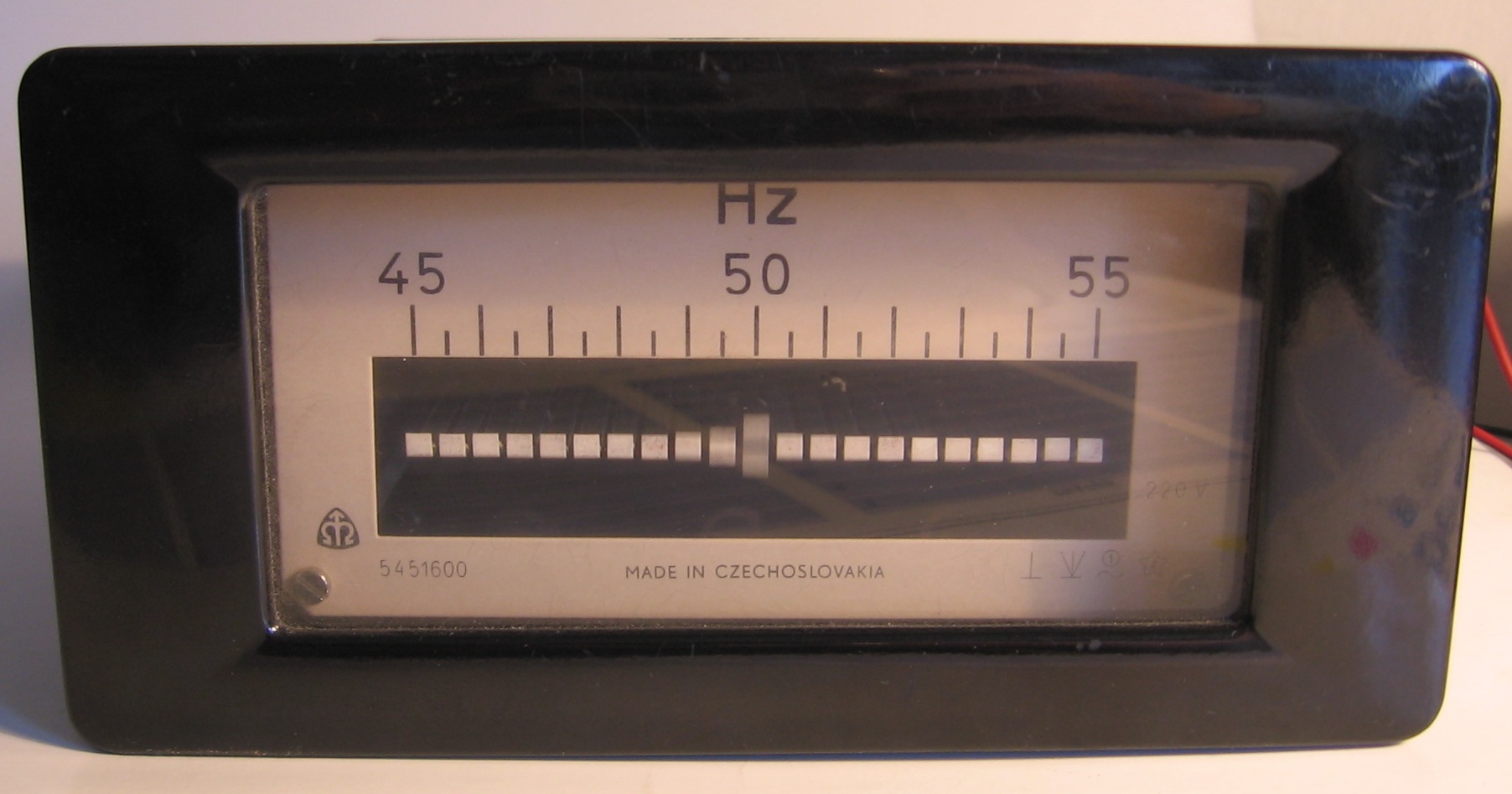
Vibrating reed indicators have been used for a low-cost display of frequency. This was typically used for a small generator set, where maintaining an output frequency of 50 Hz or 60 Hz was needed. A comb of reeds centered on this frequency would be mounted edge-on to the control panel and the vibrations of the reed with the greatest amplitude could be seen directly. The reeds used in such an indicator have their ends bent perpendicular to the rest of the reed to give a larger area to view, instead of the small cross-section of the thin metal they are made of.
Notes
References
References
- "Secret communication system".
- (2006). "Blind Landings: Low-Visibility Operations in American Aviation, 1918-1958". Johns Hopkins University Press.
- (1928). "Design of Tuned Reed Course Indicators for Aircraft Radiobeacon". Bureau of Standards Journal of Research.
This article was imported from Wikipedia and is available under the Creative Commons Attribution-ShareAlike 4.0 License. Content has been adapted to SurfDoc format. Original contributors can be found on the article history page.
Ask Mako anything about Reed receiver — get instant answers, deeper analysis, and related topics.
Research with MakoFree with your Surf account
Create a free account to save articles, ask Mako questions, and organize your research.
Sign up freeThis content may have been generated or modified by AI. CloudSurf Software LLC is not responsible for the accuracy, completeness, or reliability of AI-generated content. Always verify important information from primary sources.
Report