From Surf Wiki (app.surf) — the open knowledge base
Loading gauge
Maximum dimensions for railway vehicles and their loads

Maximum dimensions for railway vehicles and their loads
A loading gauge is a diagram or physical structure that defines the maximum height and width of railway vehicles and their loads. The loading gauge is to ensure that rail vehicles can pass safely through tunnels and under bridges, and keep clear of platforms, trackside buildings and other structures. Classification systems vary between different countries, and loading gauges may vary across a network, even if the track gauge is uniform.
The term loading gauge can also be applied to the maximum size of road vehicles in relation to tunnels, overpasses and bridges, and doors into automobile repair shops, bus garages, filling stations, residential garages, multi-storey car parks and warehouses.
A related but separate gauge is the structure gauge, which sets limits to the extent that bridges, tunnels and other infrastructure can encroach on rail vehicles. The difference between these two gauges is called the clearance. The specified amount of clearance makes allowance for the oscillation of rail vehicles at speed.
Overview

The loading gauge governs the size of passenger carriages, goods wagons (freight cars) and shipping containers that can travel on the relevant section of railway track. It varies between rail systems around the world and can even vary within a single railway system.
Over time, there has been a trend towards less restrictive loading gauges and greater standardization of them. Some older systems and lines have had their structure gauges expanded by raising bridges, increasing the height and width of tunnels and making other necessary alterations. Containerisation, and a trend towards larger shipping containers, has led rail operators to increase loading and structure gauges to compete with road haulage.
The term "loading gauge" can also refer to a physical structure, sometimes using electronic detectors using light beams on an arm or gantry placed over the exit lines of goods yards or at the entry point to a restricted part of a network. The devices ensure that loads stacked on open or flat wagons stay within the height/shape limits of the line's bridges and tunnels, and prevent out-of-gauge rolling stock entering a stretch of line with a smaller loading gauge. Compliance with a loading gauge can be checked using a clearance car. In the past, they were simple wooden frames or physical feelers mounted on rolling stock. More recently, laser beams have been used.
The loading gauge is the maximum size of rolling stock. It is distinct from the minimum structure gauge, which sets limits to the size of bridges and tunnels on a rail line, allowing for engineering tolerances and the motion of rail vehicles. The difference between the two is called the clearance. The terms "dynamic envelope" or "kinematic envelope", which include factors such as suspension travel, overhang on curves (at both ends and middle) and lateral motion on the track, are sometimes used in place of loading gauge.
Railway platform height is also a consideration for the loading gauge of passenger trains. Where the two are not directly compatible, stairs may be required, which will increase loading times. Where long carriages are used at a curved platform, there will be gaps between the platform and the carriage door, causing risk. Problems increase where trains of several different loading gauges and vehicle floor heights use (or even must pass through) the same platform.
The size of load that can be carried on a railway of a particular gauge is also influenced by the design of the rolling stock. Low-deck rolling stock can sometimes be used to carry taller 9 ft shipping containers on lower gauge lines although their low-deck rolling stock cannot then carry as many containers.
Rapid transit (metro) railways generally have a smaller loading gauge, which reduces the cost of tunnel construction. Those systems have to use their own specialised rolling stock.
Out of gauge
Larger out-of-gauge loads can also sometimes be conveyed by taking one or more of the following measures:
- Operate at low speed, especially in places with limited clearance, such as platforms.
- Cross over from a track with inadequate clearance to another track with greater clearance, even if there is no signalling to allow this.
- Prevent operation of other trains on adjacent tracks.
- Use refuge loops to allow trains to operate on other tracks.
- Use of Schnabel cars (special rolling stock) that manipulate the load up and down or left and right to clear obstacles.
- Remove (and later replace) obstacles.
- Use gauntlet track to shift the train to side or center.
- For locomotives that are too heavy, ensure that fuel tanks are nearly empty.
- Turn off power in overhead wiring or in the third rail (use diesel locomotive)
- Permanently adapt a certain route to larger gauge if there is repeated need for such trains.
History
The loading gauge on the main lines of Great Britain, most of which were built before 1900, is generally smaller than in other countries. In mainland Europe, the slightly larger Berne gauge (Gabarit passe-partout international, PPI) was agreed to in 1913 and came into force in 1914.{{cite web |author-link=Douglas Self |url-status=live|archive-url=https://web.archive.org/web/20160303201424/http://www.aqpl43.dsl.pipex.com/MUSEUM/LOCOLOCO/loadgauge/loadgauge.htm|archive-date=3 March 2016}} As a result, British trains have noticeably and considerably smaller loading gauges and, for passenger trains, smaller interiors, despite the track being standard gauge, which is in line with much of the world.
This often results in increased costs for purchasing new trainsets or locomotives as they must be specifically designed for the existing British network, rather than being purchased "off-the-shelf". For example, the new trains for HS2 have a 50% premium applied to the "classic compatible" sets that will be "compatible" with the current (or "classic") rail network loading gauge as well as the HS2 line. The "classic compatible" trainsets will cost £40million per trainset whereas the HS2-only stock (built to European loading gauge and only suitable to operate on HS2 lines) will cost £27M per trainset despite the HS2-only stock being physically larger.
It was recognized even during the nineteenth century that this would pose problems and countries whose railroads had been built or upgraded to a more generous loading gauge pressed for neighboring countries to upgrade their own standards. This was particularly true in continental Europe where the Nordic countries and Germany with their relatively generous loading gauge wanted their cars and locomotives to be able to run throughout the standard gauge network without being limited to a small size. France, which at the time had the most restrictive loading gauge ultimately compromised giving rise to Berne gauge which came into effect just before World War I.
Military railways were often built to particularly high standards, especially after the American Civil War and the Franco-Prussian War showed the importance of railroads in military deployment as well as mobilization. The German Empire was particularly active in the construction of military railways which were often built with great expense to be as flat, straight and permissive in loading gauge as possible while bypassing major urban areas, making those lines of little use to civilian traffic, particularly civilian passenger traffic. However, all those aforementioned factors have in some cases led to the subsequent abandoning of those railroads.
The loading gauge affected tank design, with the 1945 British Centurion tank the first British tank allowed to exceed the restricted British loading gauge. The 1944 German Tiger II tank had to be changed to narrower transport tracks instead of battle tracks for transport by rail.
Standard loading gauges for standard track gauge lines
International Union of Railways (UIC) Gauge

The International Union of Railways (UIC) has developed a standard series of loading gauges named A, B, B+ and C.
- PPI – the predecessor of the UIC gauges had the maximum dimensions 3.15 by with an almost round roof top.
- UIC A: The smallest (slightly larger than PPI gauge). Maximum dimensions 3.15 by.
- UIC B: Slightly larger than the UIC on the roof level. Maximum dimensions 3.15 by.{{cite journal |access-date=2 July 2013 |url-status=dead |archive-url=https://web.archive.org/web/20120907121105/http://www.rgsonline.co.uk/Railway_Group_Standards/Infrastructure/Guidance%20Notes/GEGN8573%20Iss%203.pdf |archive-date=7 September 2012
- UIC B+: New structures in France are being built to UIC B+. Up to 4.28 m has a shape to accommodate tractor-trailers loaded with ISO containers.
- UIC C: The Central European gauge. In Germany and other central European countries, the railway systems are built to UIC C gauges, sometimes with an increment in the width, allowing Scandinavian trains to reach German stations directly, originally built for Soviet freight cars. Maximum dimensions 3.15 by.
Europe
European standards
In the European Union, the UIC directives were supplanted by ERA Technical Specifications for Interoperability (TSI) of European Union in 2002, which has defined a number of recommendations to harmonize the train systems. The TSI Rolling Stock (2002/735/EC) has taken over the UIC Gauges definitions defining Kinematic Gauges with a reference profile such that Gauges GA and GB have a height of 4.35 m (they differ in shape) with Gauge GC rising to 4.70 m allowing for a width of 3.08 m of the flat roof. All cars must fall within an envelope of 3.15 m wide on a 250 m radius curve. The TGVs, which are 2.9 m wide, fall within this limit.
The designation of a GB+ loading gauge refers to the plan to create a pan-European freight network for ISO containers and trailers with loaded ISO containers. These container trains (piggy-back trains) fit into the B envelope with a flat top so that only minor changes are required for the widespread structures built to loading gauge B on continental Europe. A few structures on the British Isles were extended to fit with GB+ as well, where the first lines to be rebuilt start at the Channel Tunnel.
Owing to their historical legacies, many member states' railways do not conform to the TSI specification. For example, Britain's role at the forefront of railway development in the 19th century has condemned it to the small infrastructure dimensions of that era. Conversely, the loading gauges of countries that were satellites of the former Soviet Union are much larger than the TSI specification. Other than for GB+, they are not likely to be retrofitted, given the enormous cost and disruption that would be entailed.
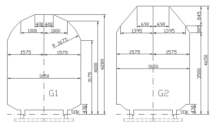
| Loading gauge | Static reference profile | Kinematic reference profile | Comments | url=http://www.uic.org/etf/codex/codex-detail.php?langue_fiche=E&codeFiche=506 | title=Leaflet 506 – Rules governing application of the enlarged GA, GB, GB1, GB2, GC and GI3 gauges | access-date=27 May 2009 | url-status=dead | archive-url=https://web.archive.org/web/20111007123000/http://www.uic.org/etf/codex/codex-detail.php?langue_fiche=E&codeFiche=506 | archive-date=7 October 2011}} | RIV | Width | Height | Width | Height |
|---|---|---|---|---|---|---|---|---|---|---|---|---|---|---|
| G1 / UIC 505-1 | T 11 | 3.150 m | 4.280 m | 3.290 m | 4.310 m | Static profile also known as Berne gauge, PPI or OSJD 03-WM. | ||||||||
| GA | T 12 | 4.320 m | 4.350 m | |||||||||||
| GB | T 13 | |||||||||||||
| GB1 / GB+ | ||||||||||||||
| GB2 | ||||||||||||||
| G2 | T 14 | 4.650 m | 4.680 m | Formerly UIC C; Static profile also known as OSJD 02-WM. | ||||||||||
| DE3 | not defined | Expansion for G2, part of TEN-T regulations. | ||||||||||||
| GC | 3.150 m | 4.650 m | 4.700 m | Formerly UIC C1. | ||||||||||
| SE-A | 3.400 m | 4.650 m | 3.600 m | 4.790 m | ||||||||||
| SE-C | 3.600 m | 4.830 m | 3.960 m | 4.990 m | High-capacity rail corridor standard for Øresund Bridge and Fehmarn Belt Tunnel |
Double-decker carriages


A specific example of the value of these loading gauges is that they permit double decker passenger carriages. Although mainly used for suburban commuter lines, France is notable for using them on its high speed TGV services: the SNCF TGV Duplex carriages are 4303 mm high,{{cite conference | conference-url = | trans-title = rolling stock
Great Britain
Great Britain has (in general) the most restrictive loading gauge (relative to track gauge) in the world. That is a legacy of the British railway network being the world's oldest, and of having been built by a large number of different private companies, each with different standards for the width and height of trains. After nationalisation, a standard static gauge W5 was defined in 1951 that would virtually fit everywhere in the network. The W6 gauge is a refinement of W5, and the W6a changed the lower body to accommodate third-rail electrification. While the upper body is rounded for W6a with a static curve, there is an additional small rectangular notch for W7 to accommodate the transport of 2.44 m ISO containers, and the W8 loading gauge has an even larger notch spanning outside of the curve to accommodate the transport of 2.6 m ISO containers. While W5 to W9 are based on a rounded roof structure, those for W10 to W12 define a flat line at the top and, instead of a strict static gauge for the wagons, their sizes are derived from dynamic gauge computations for rectangular freight containers.
Network Rail uses a W loading gauge classification system of freight transport ranging from W6A (smallest) through W7, W8, W9, W9Plus, W10, W11 to W12 (largest). The definitions assume a common "lower sector structure gauge" with a common freight platform at 1100 mm above rail.
In addition, gauge C1 provides a specification for standard coach stock, gauge C3 for longer Mark 3 coaching stock, gauge C4 for Pendolino stock and gauge UK1 for high-speed rail. There is also a gauge for locomotives. The size of container that can be conveyed depends both upon the size of the load that can be conveyed and the design of the rolling stock.
- W6A: Available over the majority of the British rail network.
- W8: Allows standard 2.6 m high shipping containers to be carried on standard wagons.
- W9: Allows 2.9 m high Hi-Cube shipping containers to be carried on "Megafret" wagons that have lower deck height with reduced capacity. which are designed to carry Euro-pallets efficiently
- W10: Allows 2.9 m high Hi-Cube shipping containers to be carried on standard wagons and also allows 2.5 m wide Euro shipping containers. Larger than UIC A.
- W11: Little used but larger than UIC B.
- W12: Slightly wider than W10 at 2.6 m to accommodate refrigerated containers. Recommended clearance for new structures, such as bridges and tunnels.
- UIC GC: Channel Tunnel and Channel Tunnel Rail Link to London; with proposals to upgrade the Midland Main Line northwards from London to GB+ standards.
A strategy was adopted in 2004 to guide enhancements of loading gauges and in 2007 the freight route utilisation strategy was published. That identified a number of key routes where the loading gauge should be cleared to W10 standard and, where structures are being renewed, that W12 is the preferred standard.
Height and width of containers that can be carried on GB gauges (height by width). Units as per source material.
- W9: 9 ft by 2.6 m
- W10: 9 ft by 2.5 m
- W11: 9 ft by 2.55 m
- W12: 9 ft by 2.6 m
Tube lines
- The City and South London Railway was built with tunnels of only 10 ft diameter. Enlarged for Northern line to 12 ft
- The Central line has tunnels of 11 ft, increasing on curves and narrowing to 11 ft near stations. This makes Central line trains unique on the London Underground because although the rolling stock's loading gauge is the same as the other Tube lines, the smaller tunnels require the positive conductor rail to be 1.6 in higher than on all other lines.
A Parliamentary committee headed by James Stansfeld then reported on 23 May 1892, "The evidence submitted to the Committee on the question of the diameter of the underground tubes containing the railways has been distinctly in favour of a minimum diameter of 11 ft". After that, all tube lines were at least that size.
- Piccadilly line with tunnels of 12 ft
- Victoria line with tunnels of 12 ft; enlarged to reduce air friction.
- Glasgow Subway with tunnels of 11 ft and a unique track gauge of only .
- Tyne and Wear Metro with tunnels of 15 ft; built to mainline rail network standards.
Sweden
The Swedish Transport Administration (Trafikverket) has largely replaced static reference profiles with kinematic reference profiles. The two main standards are SE-A and SE-C. The SE-B profile has been withdrawn, as all track has been upgraded to at least SE-A. SE-C is required for all new construction and, when economically viable, during upgrades. Some SE-A track has been partially upgraded to SE-C and accommodates profiles such as P/C 450 (P/C 447) and GC or loads such as SECU containers.
Both SE-A and SE-C are defined for straight track, with the corresponding structure gauge. On curved track, the structure gauge is widened to allow the 24-metre reference vehicle to pass. By European standards, SE-C is unusually large, permitting vehicles up to 24 metres long and almost 4 metres wide. However, vehicles with softer suspension that allows greater lateral movement must be narrower to remain within the kinematic reference profile.
Netherlands
In the Netherlands, a similar shape to the UIC C is used that rises to 4.70 m in height. The trains are wider allowing for 3.40 m width similar to Sweden. About one third of the Dutch passenger trains use bilevel rail cars. However, Dutch platforms are much higher than Swedish ones.
Betuweroute
- Betuweroute: 4.10 by to allow double stacked container trains in the future. The present overhead line does not allow this height, as it has to follow standards.
Channel Tunnel
- Channel Tunnel: 4.10 by
North America
Freight
The American loading gauge for freight cars on the North American rail network is generally based on standards set by the Association of American Railroads (AAR) Mechanical Division. The most widespread standards are AAR Plate B and AAR Plate C, but higher loading gauges have been introduced on major routes outside urban centers to accommodate rolling stock that makes better economic use of the network, such as auto carriers, hi-cube boxcars, and double-stack container loads. The maximum width of 10 ft on 41 ft (AAR Plate B), 46 ft (AAR Plate C) and all other truck centers (of all other AAR Plates) are on a 441 ft radius or 13° curve. In all cases of the increase of truck centers, the decrease of width is covered by AAR Plates D1 and D2.
Listed here are the maximum heights and widths for cars. However, the specification in each AAR plate shows a car cross section that is chamfered at the top and bottom, meaning that a compliant car is not permitted to fill an entire rectangle of the maximum height and width.
| AAR | |||||||||||||||||||
|---|---|---|---|---|---|---|---|---|---|---|---|---|---|---|---|---|---|---|---|
| Plate | Width | Height | Truck centers | Comments | Image | ft in | m | ft in | m | ft in | m | ||||||||
| B | 10 ft | 15 ft | 41 ft | For longer truck centers, the width is decreased according to graph AAR Plate B-1 on a 441 ft radius curve or AAR Plate D1 | [[File:Gabarit AAR Plate-B.png | 100px | center]] | ||||||||||||
| C | 10 ft | 15 ft | with 46 ft | For longer truck centers, the width is decreased according to graph AAR Plate C-1 on a 441 ft radius curve or AAR Plate D1 | [[File:Gabarit AAR Plate-C.png | 100px | center]] | ||||||||||||
| E | 10 ft | 15 ft | with 46 ft | However the top of rail clearance is 2+3/4 in instead of 2+1/2 in. | [[File:Gabarit AAR Plate E.png | 100px | center]] | ||||||||||||
| F | 10 ft | 17 ft | with 46 ft | As with AAR Plate C but 18 in taller than AAR Plate C and 15 in taller than AAR Plate E, and the car cross section is larger at the top than AAR Plate E. | [[File:Gabarit AAR Plate F.png | 100px | center]] | ||||||||||||
| H | 10 ft | 20 ft | {{convert | 62 | ft | 7 | in | m | 2 | disp=table}} | e.g. Including the height of double stacked containers in well cars. The cross section at the bottom of the well car differs from the X section of all other AAR plates. X section at center of car Width of 10 ft only possible at the trucks | [[File:Gabarit AAR Plate-H.png | 100px | center]] | |||||
| 10 ft | 20 ft | {{convert | 63 | ft | 9 | in | m | 2 | disp=table}} | e.g. Including the height of double stacked containers in well cars. The width at greater than 63 ft covered by AAR Plate D1 | |||||||||
| The cross section at the bottom of the well car differs from all other AAR Plates. in well cars | [[File:Gabarit AAR Plate-H.png | 100px | center]] | ||||||||||||||||
| --- | 9 ft | 3 ft | 66 ft | e.g. 85 ft long flatcars, *Height of deck at center of car Width covered by AAR Plate D1. | |||||||||||||||
| 9 ft | |||||||||||||||||||
| J | 10 ft | 19 ft | 55 ft | Truck centers can be more. Widths covered by AAR Plate D1. | |||||||||||||||
| K | 10 ft | 20 ft | 65 ft | url=http://www.gbrx.com/PDFtecbulletins/GenFreightAutoMax.pdf | title=Autorack}} | ||||||||||||||
| L | 10 ft | 16 ft | 46 ft | For locomotives only | |||||||||||||||
| M | 10 ft | 16 ft | 46 ft | For locomotives only |
Technically, AAR Plate B is still the maximum height and truck center combination and the circulation of AAR Plate C is somewhat restricted. The prevalence of excess-height rolling stock, at first ~18 ft piggybacks and hicube boxcars, then later autoracks, airplane-parts cars, and flatcars for hauling Boeing 737 fuselages, as well as 20 ft high double-stacked containers in container well cars, has been increasing. This means that most, if not all, lines are now designed for a higher loading gauge. The width of these extra-height cars is covered by AAR Plate D1.
All the Class I rail companies have invested in longterm projects to increase clearances to allow double stack freight. The mainline North American rail networks of the Union Pacific, the BNSF, the Canadian National, and the Canadian Pacific, have already been upgraded to AAR Plate K. This represents over 60% of the Class I rail network.
Gallery
File:Boeing 737 fuselage train hull 3473.jpg|Boeing 737 Next Generation fuselage being transported by rail on a flatcar File:DTTX 724681 20050529 IL Rochelle.jpg|Double-stack container service requires the highest loading gauge in common use in North America. File:ETTX 905721 20050529 IL Rochelle.jpg|A Norfolk Southern autorack on a TTX flatcar also requires the highest loading gauge in common use in North America. File:Santa_Fe_TOFC_(Trailer_on_Flat_Car)_(10589289363).jpg|A Santa Fe semi-trailer carried on a flatcar as part of a TOFC train.
Passenger service

The old standard North American passenger railcar is 10 ft wide by 14 ft high and measures 85 ft over coupler pulling faces with 59 ft truck centers, or 86 ft over coupler pulling faces with 60 ft truck centers. In the 1940s and 1950s, the American passenger car loading gauge was increased to a 16 ft height throughout most of the country outside the Northeast, to accommodate dome cars and later Superliners and other bilevel commuter trains. Bilevel and Hi-level passenger cars have been in use since the 1950s, and new passenger equipment with a height of 19 ft has been built for use in Alaska and the Canadian Rockies. The structure gauge of the Mount Royal Tunnel used to limit the height of bilevel cars to 14 ft before it was permanently closed to interchange rail traffic prior to its conversion for the REM rapid transit system.
New York City Subway
The New York City Subway is an amalgamation of three former constituent companies, and while all are standard gauge, inconsistencies in loading gauge prevent cars from the former BMT and IND systems (B Division) from running on the lines of the former IRT system (A Division), and vice versa. This is mainly because IRT tunnels and stations are approximately 1 ft narrower than the others, meaning that IRT cars running on the BMT or IND lines would have platform gaps of over 8 in between the train and some platforms, whereas BMT and IND cars would not even fit into an IRT station without hitting the platform edge. Taking this into account, all maintenance vehicles are built to IRT loading gauge so that they can be operated over the entire network, and employees are responsible for minding the gap.
Another inconsistency is the maximum permissible railcar length. Cars in the former IRT system are 51 ft . Railcars in the former BMT and IND can be longer: on the former Eastern Division, the cars are limited to 60 ft, while on the rest of the BMT and IND lines plus the Staten Island Railway (which uses modified IND stock) the cars may be as long as 75 ft.
Boston (MBTA)
The Massachusetts Bay Transportation Authority's (MBTA) rapid transit system is composed of four unique subway lines; while all lines are standard gauge, inconsistencies in loading gauge, electrification, and platform height prevent trains on one line from being used on another. The first segment of the Green Line (known as the Tremont Street subway) was constructed in 1897 to take the streetcars off Boston's busy downtown streets. When the Blue Line opened in 1904, it only ran streetcar services; the line was converted to rapid transit in 1924 due to high passenger loads, but the tight clearances in the tunnel under the Boston Harbor required narrower and shorter rapid transit cars. The Orange Line was originally built in 1901 to accommodate heavy rail transit cars of higher capacity than streetcars. The Red Line was opened in 1912, designed to handle what were for a time the largest underground transit cars in the world.
Los Angeles (LACMTA)
The Los Angeles Metro Rail system is an amalgamation of two former constituent companies, the Los Angeles County Transportation Commission and the Southern California Rapid Transit District; both of those companies were responsible for planning the initial system. It is composed of two heavy rail subway lines and several light rail lines with subway sections; while all lines are standard gauge, inconsistencies in electrification and loading gauge prohibit the light rail trains from operating on the heavy rail lines, and vice versa. The LACTC-planned Blue Line was opened in 1990 and partially operates on the route of the Pacific Electric interurban railroad line between downtown Los Angeles and Long Beach, which used overhead electrification and street-running streetcar vehicles. The SCRTD-planned Red Line (later split into the Red and Purple lines) was opened in 1993 and was designed to handle high-capacity heavy rail transit cars that would operate underground. Shortly after the Red Line began operations, the LACTC and the SCRTD merged to form the LACMTA, which became responsible for planning and construction of the Green, Gold, Expo, and K lines, as well as the D Line Extension and the Regional Connector.
Asia
Major trunk raillines in East Asian countries, including China, North Korea, South Korea, as well as the Shinkansen of Japan, have all adopted a loading gauge of 3,400 mm maximum width and can accept the maximum height of 4,500 mm.
China
The maximum height, width, and length of general Chinese rolling stock are 4,800 mm, 3,400 mm and 26 m respectively, with an extra out-of-gauge load allowance of height and width 5300 by with some special shape limitation, corresponding to a structure gauge of 5500 by. China is building numerous new railways in sub-Saharan Africa and Southeast Asia (such as in Kenya and Laos), and these are being built to "Chinese Standards". This presumably means track gauge, loading gauge, structure gauge, couplings, brakes, electrification, etc. An exception may be double stacking, which has a height limit of 5,850 mm. Metre gauge in China has a gauge of 3050 mm.
Japan, standard gauge

Translation of legend:
- Blue: Rural railway vehicle gauge (Rural Railway Construction Rules 1919)
- Grey: Conventional Cape gauge (3 ft 6 in track gauge) railway vehicle limits (Ordinary Railway Structure Rules 1987)
- Figures in () are previous Cape gauge rolling stock limits (Railway Construction Rules 1900)
- Green: Shinkansen vehicle limits
Trains on the Shinkansen network operate on track and have a loading gauge of 3,400 mm maximum width and 4,500 mm maximum height. This allows the operation of double-deck high-speed trains.
Mini Shinkansen (former conventional narrow gauge lines that have been regauged into ) and some private railways in Japan (including some lines of the Tokyo subway and all of the Osaka Metro) also use standard gauge; however, their loading gauges are different.
The rest of Japan's system is discussed under narrow gauge, below.
Hong Kong
South Korea
The body frame may have a maximum height of 4,500 mm and a maximum width of 3,400 mm with additional installations allowed up to 3,600 mm. That width of 3,400 mm is only allowed above 1250 mm as the common passenger platforms are built to former standard trains of 3200 mm in width.
Philippines
There is currently no uniform standard for loading gauges in the country and both loading gauges and platform heights vary by rail line.
The North–South Commuter Railway allows passenger trains with a carbody width of 3100 mm and a height of 4300 mm. Additional installations shall also be allowed up to 3300 mm at a platform height of 1100 mm where it is limited by half-height platform screen doors. Above the platform gate height of 1200 mm above the platforms, out-of-gauge installations can be further maximized to the Asian standard at 3400 mm.
Meanwhile, the PNR South Long Haul will follow the Chinese gauge and therefore use a larger carbody width of 3300 mm from the specifications of passenger rolling stock, and a height of 4770 mm per P70-type boxcar specifications.
Africa
Some of the new railways being built in Africa allow for double-stacked containers, the height of which is about 5,800 mm depending on the height of each container 2,438 mm or 2,900 mm plus the height of the deck of the flat wagon about 1,000 mm totalling 5,800 mm. This exceeds the China height standard for single stacked containers of 4,800 mm. Additional height of about 900 mm is needed for overhead wires for 25 kV AC electrification.
The permissible width of the new African standard gauge railways is 3400 mm.
Australia
The standard gauge lines of New South Wales Government Railways allowed for a width of 9 ft until 1910, after a conference of the states created a new standard of 10 ft, with corresponding increase in track centres. The narrow widths have mostly been eliminated, except, for example, at the mainline platforms at Gosford and some sidings. The longest carriages are 72 ft.
The Commonwealth Railways adopted the national standard of 10 ft when they were established in 1912, although no connection with New South Wales was made until 1970.
A T set of the late 1980s was 3000 mm wide. Track centres from Penrith to Mount Victoria and Gosford and Wyong have been gradually widened to suit. The D set intercity sets are however 3100 mm wide, so further, costly modification was required beyond Springwood, which was completed in 2020.
The Kwinana, Eastern and Eastern Goldfields lines in Western Australia were built with a loading gauge of 12 ft wide and 20 ft tall to allow for trailer on flatcar (TOFC) traffic when converted to dual gauge in the 1960s.
Broad gauge
Main article: Broad-gauge railway
Indian Gauge
- The smallest loading gauge for a gauge railway is the Delhi Metro, which is 3250 mm wide and 4140 mm tall.
- Indian Railways has a maximum passenger loading gauge of 3660 mm and a freight loading gauge of 3,250 mm, with development allowing a width of 3710 mm.
- Sri Lanka Railways has a loading gauge of between 3200 mm and 4267 mm.
5 ft and Russian gauge
In Finland, rail cars can be up to 3.4 m wide with a permitted height from 4.37 m on the sides to 5.3 m in the centre. The track gauge is , differing 4 mm from the Russian track gauge.
The Russian loading gauges are defined in standard GOST 9238 (ГОСТ 9238–83, ГОСТ 9238–2013) with the current 2013 standard named "Габариты железнодорожного подвижного состава и приближения строений" (construction of rolling stock clearance diagrams [official English title]). It was accepted by the Interstate Council for Standardization, Metrology and Certification to be valid in Russia, Belarus, Moldova, Ukraine, Uzbekistan and Armenia. Loading gauge is generally wider than Europe, but with many exception standards.
- T: standard loading gauge
- T: 5,300 mm height, 3,750 mm width
- Tc: 5,200 mm height, 3,750 mm width: for tank and dumper cars
- Tpr: 5,300 mm height, 3,500 mm width: extra out-of-gauge cargo load for main tracks
- 1-T: guaranteed loading gauge for all ex-USSR lines including old tunnels.
- 1-T: 5,300 mm height, 3,400 mm width
- VM: for international stock for 1435 mm lines, standards for different lines
- 0-VM: 4,650 mm height, 3,250 mm width
- 1-VM: 4,700 mm height, 3,400 mm width
- 02-VM: 4,650 mm height, 3,150 mm width
- 03-VM: 4,280 mm height, 3,150 mm width
The standard defines static envelopes for trains on the national network as T, Tc and Tpr. The static profile 1-T is the common standard on the complete 1520 mm rail network including the CIS and Baltic states. The structure clearance is given as S, Sp and S250. There is a tradition that structure clearance is much bigger than the common train sizes. For international traffic, the standard references the kinematic envelope for GC and defines a modified GCru for its high-speed trains. For other international traffic, there are 1-T, 1-VM, 0-VM, 02-VM and 03-VMst/03-VMk for the trains and 1-SM for the structure clearance.
The main static profile T allows for a maximum width of 3750 mm rising to a maximum height of 5300 mm. The profile Tc allows that width only at a height of 3000 mm, requiring a maximum of 3400 mm below 1270 mm, which matches with the standard for train platforms (with a height of 1100 mm). The profile Tpr has the same lower frame requirement but reduces the maximum upper body width to 3500 mm. The more universal profile 1-T has the complete body at a maximum width of 3400 mm still rising to a height of 5300 mm. Exceptions shall be double-stacking, maximum height shall be 6150 mm or 6400 mm.
The structure gauge S requires buildings to be placed at minimum of 3100 mm from the track centreline. Bridges and tunnels must have a clearance of at least 4900 mm wide and 6400 mm high. The structure gauge Sp for passenger platforms allows 4900 mm only above 1100 mm (the common platform height) requiring a width of 3840 mm below that line. The exceptions shall be double-stacking, minimum overhead wiring height must be 6500 mm (for maximum vehicle height of 6150 mm) or 6750 mm (for maximum vehicle height of 6400 mm).
The main platform is defined to have a height of 1100 mm at a distance of 1920 mm from the center of the track to allow for trains with profile T. Low platforms at a height of 200 mm may be placed at 1745 mm from the center of the track. A medium platform is a variant of the high platform but at a height of 550 mm. That matches with the Tc, Tpr and the universal 1-T loading gauge.
Iberian gauge
Main article: Iberian-gauge railways
In Portugal, there are three railway loading gauge standards for conventional (iberian gauge) railways: Gabarito PT b, Gabarito PT b+ and Gabarito PT c. Gabarito PT b (also called CPb) and Gabarito PT b+ (also called CPb+) allow rail cars to be 3.44 m (11 ft 3.5 in) wide with a permitted height of 4.5 m (14 ft 9 in), although CPb+ has a slightly larger profile area. Gabarito PT c allows rail cars to be 3.44 m (11 ft 3.5 in) wide with a permitted height of 4.7 m (15 ft 5 in). Gabarito PT b and PT b+ are both used, being PT b+ more common overall. Gabarito PT c is currently not used. In Lisbon, there is a suburban railway line, the Cascais Line, that follows a fourth non-standard loading gauge.
Irish Gauge
Main article: 5 ft 3 in gauge railways
Ireland and Northern Ireland
Main article: Iarnród Éireann, NI Railways
Australia
Brazil
Narrow gauge
Main article: Narrow gauge railways
Narrow gauge railways generally have a smaller loading gauge than standard gauge ones, and this is a major reason for cost savings rather than the railgauge itself. For example, the Lyn locomotive of the Lynton and Barnstaple Railway is 7 ft wide. By comparison, several standard gauge 73 class locomotives of the NSWR, which are 9 ft wide, have been converted for use on cane tramways, where there are no narrow bridges, tunnels or track centres to cause trouble. The 6E1 locomotive of the South African Railways are 9 ft wide.
A large numbers of railways using the gauge used the same rolling stock plans, which were 7 ft wide.
Great Britain
Ffestiniog Railway
Main article: Ffestiniog Railway
- gauge =
- width (brakevan mirrors) = 6 ft
- width (brakevan body) = 6 ft
- height = 5 ft
- length = (carriage) 36 ft
Lynton and Barnstaple Railway
Main article: Lynton and Barnstaple Railway

- gauge =
- Lyn (locomotive) over headstocks
- length = 23 ft
- width = 7 ft
- height = 8 ft
- Passenger
- length = 39 ft
- width = 6 ft wide,
- width over steps = 7 ft
- height = 8 ft
Japan, narrow gauge
Main article: Rail transport in Japan
Translation of legend:
- Blue: Rural railway vehicle gauge (Rural Railway Construction Rules 1919)
- Grey: Conventional Cape gauge (3ft 6in track gauge) railway vehicle limits (Ordinary Railway Structure Rules 1987)
- Figures in () are previous Cape gauge rolling stock limits (Railway Construction Rules 1900)
- Green: Shinkansen vehicle limits
The Japanese national network operated by Japan Railways Group employs narrow gauge . The maximum allowed width of the rolling stock is 3000 mm and maximum height is 4100 mm; however, a number JR lines were constructed as private railways prior to nationalisation in the early 20th century, and feature loading gauges smaller than the standard. These include the Chūō Main Line west of Takao, the Minobu Line, and the Yosan Main Line west of Kan'onji (3900 mm height). Nevertheless, advances in pantograph technology have largely eliminated the need for separate rolling stock in these areas.
There are many private railway companies in Japan and the loading gauge is different for each company.
South Africa
Main article: Rail transport in South Africa, Transnet Freight Rail, Passenger Rail Agency of South Africa
The South African national network employs gauge. The maximum width of the rolling stock is 3048 mm and maximum height is 3962 mm, which is greater than the normal British loading gauge for standard gauge vehicles.
New Zealand
Main article: Rail transport in New Zealand, KiwiRail
The railways use gauge. The maximum width of the rolling stock is 2830 mm and maximum height is 3815 mm.
Other
gauge for the United Kingdom and Sierra Leone:
- Minimum radius: 132 ft
- Width: 7 ft (see Everard Calthrop)
- Wagon length (freight): 25 ft over headstocks
- Wagon length (passenger): 40 ft over headstocks
- Tank engine length: 29 ft over headstocks
Structure gauge
Main article: Structure gauge

The structure gauge, which refers to the dimensions of the lowest and narrowest bridges or tunnels of the track, complements the loading gauge, which specifies the tallest and widest allowable vehicle dimensions. There is a gap between the structure gauge and loading gauge, and some allowance needs to be made for the dynamic movement of vehicles (sway) to avoid mechanical interference causing equipment and structural damage.
Out of gauge
While it may be true that trains of a particular loading gauge can travel freely over tracks of a matching structure gauge, in practice, problems can still occur. In an accident at Moston station, an old platform not normally used by freight trains was hit by a train that wasn't within its intended W6a gauge because two container fastenings were hanging over the side. Analysis showed that the properly configured train would have passed safely even though the platform couldn't handle the maximum design sway of W6a. Accepting reduced margins for old construction is normal practice if there have been no incidents but if the platform had met modern standards with greater safety margin the out of gauge train would have passed without incident.
Trains larger than the loading gauge, but not too large, can operate if the structure gauge is carefully measured, and the trip is subject to various special regulations.
Gallery
File:BS Ladelehre Westbahnhof.JPG|German equipment outline gauge File:Lademass.jpg|Template to check if the load is exactly within the loading gauge File:Loading gauge at Moccone.jpg|Equipment outline gauge at Moccone File:Loading Gauge Eritrea.jpg|Eritrean loading gauge
References
References
- "Glossary". Network Rail.
- "European Loading Gauges".
- "HS2 Cost and Risk Model Report".
- (April 1992). "European Loading Gauges". Modern Railways.
- "Strategic Freight Network: The Longer-Term Vision". Department for Transport.
- "EUR-Lex - 32002D0735 - EN - EUR-Lex".
- Mike Smith. (2003). "Track Gauge & Loading Gauge".
- "Leaflet 506 – Rules governing application of the enlarged GA, GB, GB1, GB2, GC and GI3 gauges".
- EUR-Lex. (28 July 2006). "TSI CR WAG; 02006D0861-20130124; Annex C: Track interaction and gauging".
- (1 July 2014). "Verladerichtlinien der DB Schenker Rail AG (UIC – Verladerichtlinien); Tafel 1 Sammlung der Lademasse".
- Jacques Molinari. (April 1999). "Transport combiné et infrastructures ferroviaires; Compléments 1 – Terminologie – Chargements – Gabarits – Institutions".
- (December 2014). "Øresund and Fehmarnbelt high-capacity rail corridor standards updated". Journal of Rail Transport Planning & Management.
- (January 2013). "Gauging - The V/S SIC Guide to British gauging practice". [[Rail Safety and Standards Board]] (RSSB).
- (September 2007). "Freight Opportunities Stage 2 Part 3 – Available Space Assessment – ISO Container Routes". Rail and Safety Standards Board.
- (January 2013). "The V/S SIC Guide to British gauging practice". Rail and Safety Standards Board.
- "GE/GN8573".
- "Business Plan 2004 – Network Capability". Network Rail.
- "Felixstowe South reconfiguration inspector's report, Strategic Rail Authority submission". Department for Transport.
- "Megafret".
- "TEN PROPOSED ENHANCEMENT SCHEMES IN SCOTLAND". Freight on rail.
- "Standard Shipping Containers". Container container.
- "24 November 2006 Freight RUS Consultation Response National RUS". Central Railways.
- "Freight RUS".
- "New SRA Gauging Policy Aims to Make Best Use of Network Capability". Department for Transport.
- (February 1959). "The Size of the Tube".
- ""[TRVINFRA-00398 Krav Version 2.0]"". Trafikverket.
- (1970). "Car and Locomotive Cyclopedia of American Practice". Association of American Railroads Mechanical Division.
- [https://my.aar.org/OTLR/Documents/Section%201/Section1AppendixA_20200826.pdf Preload Inspection Checklist and Equipment Plate Diagrams] {{webarchive. link. (February 24, 2021)
- "Clearance maps for CSX, a typical major carrier".
- (1984). "Car and Locomotive Cyclopedia of American Practice". Association of American Railroads Mechanical Division.
- "Archived copy".
- (31 October 2011). "Guide to Railcars".
- "Archived copy".
- (December 2023). "Autorack}}{{Dead link".
- "Guide to Railcars".
- "Railway Line Clearances and Car Dimensions including Weight Limitations of Railroads in the United States, Canada, Mexico and Cuba". Railway Line Clearances and Car Dimensions Including Weight Limitations of Railroads in the United States, Canada, Mexico and Cuba..
- (2 August 2017). "NYC Fun Facts: Not All NYC Subway Trains Are the Same Size".
- "Glossary }} {{small".
- Clarke, Bradley. (1981). "The Boston Rapid Transit Album". Boston Street Railway Association.
- (1979). "Moving millions : an inside look at mass transit". Harper & Row.
- 久保田博. [[グランプリ出版]]. (13 February 1997)
- National Standard GB146.1–83 Rolling stock gauge for standard gauge railways
- [[Janes World Railways]]
- link. [[Ministry of Land, Infrastructure, Transport and Tourism]]
- (2021-04-06). "Foreign Assisted Projects".
- [https://www.smh.com.au/national/nsw/new-intercity-trains-too-wide-for-rail-line-to-stations-in-blue-mountains-20161005-grvmns.html New intercity trains too wide for rail line to stations in Blue Mountains] ''[[Sydney Morning Herald]]'' 5 October 2016
- Madigan, Damien. (2020-07-24). "Rail upgrade completed to fit new trains on Blue Mountains Line". [[Blue Mountains Gazette]].
- [https://web.archive.org/web/20211118152224/https://portal.engineersaustralia.org.au/system/files/engineering-heritage-australia/nomination-title/HRP.WA%20Standard%20Gauge%20Railway%20Kalgoorlie%20to%20Perth.Nomination.Dec%202012.pdf Nomination of Western Australian Standard Gauge Railway for an Engineering Heritage Australia Heritage Recognition Award] [[Engineers Australia]] September 2011
- Mundrey. (2000-09-01). "Railway Track Engineering". Tata McGraw-Hill Education.
- "Archived copy".
- [http://www.unescap.org/sites/default/files/tarsc-fulltext_1980.pdf DEVELOPMENT OF THE TRANS-ASIAN RAILWAY TRANS-ASIAN RAILWAY IN THE SOUTHERN CORRIDOR OF ASIA-EUROPE ROUTES]
- (15 December 2009). "Lastprofiler Finland". Green Cargo.
- (1 July 2014). "ГОСТ 9238-2013".
- "ГОСТ 9238-83 Габариты приближения строений и подвижного состава железных дорог колеи 1520 (1524) мм".
- Boyd, James. (17 October 2002). "Festiniog Railway".
- (17 April 1873). "The Festiniog Railway". [[Rockhampton Bulletin]].
- Hiroshi Kubota. (13 February 1997). "Railway Engineering Handbook". Grand Prix publishing.
- (12 April 2013). "National Rail System Standard 6 – Engineering Interoperability Standards". KiwiRail.
- ''[[The Railway Magazine]]'' April 2015, p12
- (17 February 2015). "Here is a platform alteration". rail.co.uk.
- (7 October 2015). "Report 17/2015: Trains struck platform at Moston, Manchester". Rail Accident Investigation Branch.
This article was imported from Wikipedia and is available under the Creative Commons Attribution-ShareAlike 4.0 License. Content has been adapted to SurfDoc format. Original contributors can be found on the article history page.
Ask Mako anything about Loading gauge — get instant answers, deeper analysis, and related topics.
Research with MakoFree with your Surf account
Create a free account to save articles, ask Mako questions, and organize your research.
Sign up freeThis content may have been generated or modified by AI. CloudSurf Software LLC is not responsible for the accuracy, completeness, or reliability of AI-generated content. Always verify important information from primary sources.
Report