From Surf Wiki (app.surf) — the open knowledge base
Fire-control system
Ranged weapon assistance system

Ranged weapon assistance system
A fire-control system (FCS) is an integrated system of components that assists a gunner in executing tasks needed to achieve accurate firing by means of full or semi automation. It performs the same task as a human gunner firing a weapon, but attempts to do so faster and more accurately.
Naval fire control
Origins
The original fire-control systems were developed for ships.
The early history of naval fire control was dominated by the engagement of targets within visual range (also referred to as direct fire). In fact, most naval engagements before 1800 were conducted at ranges of 20 to. Even during the American Civil War, the famous engagement between and was often conducted at less than 100 yd range.{{cite web |access-date = 2006-08-26 |archive-url = https://web.archive.org/web/20060713014755/http://www.monitorcenter.org/history/chronology/chronology2.php |archive-date = 2006-07-13
Rapid technical improvements in the late 19th century greatly increased the range at which gunfire could remain effective. Rifled guns of much larger size firing explosive shells of lighter relative weight (compared to all-metal balls) so increased the range of the guns that the main problem became aiming them while the ship was moving on the waves. This problem was solved with the introduction of the gyroscope, which corrected this motion and provided sub-degree accuracies. Guns were now free to grow to any size, and quickly surpassed 10 in calibre by the 1890s. These guns were capable of such great range that the primary limitation was seeing the target, leading to the use of high masts on ships.
Another technical improvement was the introduction of the steam turbine which greatly increased the performance of the ships. Earlier reciprocating engine powered capital ships were capable of perhaps 16 knots, but the first large turbine ships were capable of over 20 knots. Combined with the long range of the guns, this meant that the target ship could move a considerable distance, several ship lengths, between the time the shells were fired and landed. One could no longer eyeball the aim with any hope of accuracy. Moreover, in naval engagements it is also necessary to control the firing of several guns at once.
Naval gun fire control potentially involves three levels of complexity. Local control originated with primitive gun installations aimed by the individual gun crews. Director control aims all guns on the ship at a single target. Coordinated gunfire from a formation of ships at a single target was a focus of battleship fleet operations. Corrections are made for surface wind velocity, firing ship roll and pitch, powder magazine temperature, drift of rifled projectiles, individual gun bore diameter adjusted for shot-to-shot enlargement, and rate of change of range with additional modifications to the firing solution based upon the observation of preceding shots.
The resulting directions, known as a firing solution, would then be fed back out to the turrets for laying. If the rounds missed, an observer could work out how far they missed by and in which direction, and this information could be fed back into the computer along with any changes in the rest of the information and another shot attempted.
At first, the guns were aimed using the technique of artillery spotting. It involved firing a gun at the target, observing the projectile's point of impact (fall of shot), and correcting the aim based on where the shell was observed to land, which became more and more difficult as the range of the gun increased.
Between the American Civil War and 1905, numerous small improvements, such as telescopic sights and optical rangefinders, were made in fire control. There were also procedural improvements, like the use of plotting boards to manually predict the position of a ship during an engagement.
World War I
Then increasingly sophisticated mechanical calculators were employed for proper gun laying, typically with various spotters and distance measures being sent to a central plotting station deep within the ship. There the fire direction teams fed in the location, speed and direction of the ship and its target, as well as various adjustments for Coriolis effect, weather effects on the air, and other adjustments. Around 1905, mechanical fire control aids began to become available, such as the Dreyer Table, Dumaresq (which was also part of the Dreyer Table), and Argo Clock, but these devices took a number of years to become widely deployed.{{cite book
Arthur Pollen and Frederic Charles Dreyer independently developed the first such systems. Pollen began working on the problem after noting the poor accuracy of naval artillery at a gunnery practice near Malta in 1900. Lord Kelvin, widely regarded as Britain's leading scientist first proposed using an analogue computer to solve the equations which arise from the relative motion of the ships engaged in the battle and the time delay in the flight of the shell to calculate the required trajectory and therefore the direction and elevation of the guns.
Pollen aimed to produce a combined mechanical computer and automatic plot of ranges and rates for use in centralised fire control. To obtain accurate data of the target's position and relative motion, Pollen developed a plotting unit (or plotter) to capture this data. To this he added a gyroscope to allow for the yaw of the firing ship. Like the plotter, the primitive gyroscope of the time required substantial development to provide continuous and reliable guidance. Although the trials in 1905 and 1906 were unsuccessful, they showed promise. Pollen was encouraged in his efforts by the rapidly rising figure of Admiral Jackie Fisher, Admiral Arthur Knyvet Wilson and the Director of Naval Ordnance and Torpedoes (DNO), John Jellicoe. Pollen continued his work, with occasional tests carried out on Royal Navy warships.
Meanwhile, a group led by Dreyer designed a similar system. Although both systems were ordered for new and existing ships of the Royal Navy, the Dreyer system eventually found most favour with the Navy in its definitive Mark IV* form. The addition of director control facilitated a full, practicable fire control system for World War I ships, and most RN capital ships were so fitted by mid 1916. The director was high up over the ship where operators had a superior view over any gunlayer in the turrets. It was also able to co-ordinate the fire of the turrets so that their combined fire worked together. This improved aiming and larger optical rangefinders improved the estimate of the enemy's position at the time of firing. The system was eventually replaced by the improved "Admiralty Fire Control Table" for ships built after 1927.
World War II
Main article: Ship gun fire-control system
During their long service life, rangekeepers were updated often as technology advanced, and by World War II they were a critical part of an integrated fire-control system. The incorporation of radar into the fire-control system early in World War II provided ships the ability to conduct effective gunfire operations at long range in poor weather and at night. For U.S. Navy gun fire control systems, see ship gun fire-control systems.
The use of director-controlled firing, together with the fire control computer, removed the control of the gun laying from the individual turrets to a central position; although individual gun mounts and multi-gun turrets would retain a local control option for use when battle damage limited director information transfer (these would be simpler versions called "turret tables" in the Royal Navy). Guns could then be fired in planned salvos, with each gun giving a slightly different trajectory. Dispersion of shot caused by differences in individual guns, individual projectiles, powder ignition sequences, and transient distortion of ship structure was undesirably large at typical naval engagement ranges. Directors high on the superstructure had a better view of the enemy than a turret mounted sight, and the crew operating them were distant from the sound and shock of the guns. Gun directors were topmost, and the ends of their optical rangefinders protruded from their sides, giving them a distinctive appearance.
Unmeasured and uncontrollable ballistic factors, like high-altitude temperature, humidity, barometric pressure, wind direction and velocity, required final adjustment through observation of the fall of shot. Visual range measurement (of both target and shell splashes) was difficult prior to the availability of radar. The British favoured coincidence rangefinders while the Germans favoured the stereoscopic type. The former were less able to range on an indistinct target but easier on the operator over a long period of use, the latter the reverse.

Submarines were also equipped with fire control computers for the same reasons, but their problem was even more pronounced; in a typical "shot", the torpedo would take one to two minutes to reach its target. Calculating the proper "lead" given the relative motion of the two vessels was very difficult, and torpedo data computers were added to dramatically improve the speed of these calculations.
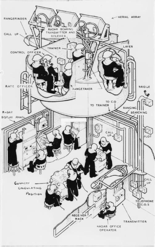
In a typical World War II British ship the fire control system connected the individual gun turrets to the director tower (where the sighting instruments were located) and the analogue computer in the heart of the ship. In the director tower, operators trained their telescopes on the target; one telescope measured elevation and the other bearing. Rangefinder telescopes on a separate mounting measured the distance to the target. These measurements were converted by the Fire Control Table into the bearings and elevations for the guns to fire upon. In the turrets, the gunlayers adjusted the elevation of their guns to match an indicator for the elevation transmitted from the Fire Control table—a turret layer did the same for bearing. When the guns were on target they were centrally fired.
Even with as much mechanization of the process, it still required a large human element; the Transmitting Station (the room that housed the Dreyer table) for HMS Hoods main guns housed 27 crew.
Directors were largely unprotected from enemy fire. It was difficult to put much weight of armour so high up on the ship, and even if the armour did stop a shot, the impact alone would likely knock the instruments out of alignment. Sufficient armour to protect from smaller shells and fragments from hits to other parts of the ship was the limit.
The performance of the analog computer was impressive. The battleship during a 1945 test was able to maintain an accurate firing solution on a target during a series of high-speed turns. |access-date = 2006-10-18 |archive-url = https://web.archive.org/web/20061120223502/http://www.navweaps.com/index_inro/INRO_BB-Gunnery_p1.htm |archive-date = 2006-11-20 |url-status = dead
Night naval engagements at long range became feasible when radar data could be input to the rangekeeper. The effectiveness of this combination was demonstrated in November 1942 at the Third Battle of Savo Island when the engaged the Japanese battleship at a range of 8400 yd at night. * Kirishima* was set aflame, suffered a number of explosions, and was scuttled by her crew. She had been hit by at least nine 16 in rounds out of 75 fired (12% hit rate).{{cite journal | access-date = 2006-08-26 The wreck of Kirishima was discovered in 1992 and showed that the entire bow section of the ship was missing.{{cite web | access-date = 2006-09-26 The Japanese during World War II did not develop radar or automated fire control to the level of the US Navy and were at a significant disadvantage.{{cite book
Post-1945
By the 1950s gun turrets were increasingly unmanned, with gun laying controlled remotely from the ship's control centre using inputs from radar and other sources.
The last combat action for the analog rangekeepers, at least for the US Navy, was in the 1991 Persian Gulf War{{cite news |access-date = 2006-09-30 |archive-url = https://web.archive.org/web/20061006223630/http://www.dogtagsrus.com/p-38%20can%20opener%20articles.htm |archive-date = 2006-10-06 |url-status = dead
Aircraft based fire control
World War II bomb sights
An early use of fire-control systems was in bomber aircraft, with the use of computing bombsights that accepted altitude and airspeed information to predict and display the impact point of a bomb released at that time. The best known United States device was the Norden bombsight.
World War II aerial gunnery sights
Simple systems, known as lead computing sights also made their appearance inside aircraft late in the war as gyro gunsights. These devices used a gyroscope to measure turn rates, and moved the gunsight's aim-point to take this into account, with the aim point presented through a reflector sight. The only manual "input" to the sight was the target distance, which was typically handled by dialing in the size of the target's wing span at some known range. Small radar units were added in the post-war period to automate even this input, but it was some time before they were fast enough to make the pilots completely happy with them. The first implementation of a centralized fire control system in a production aircraft was on the B-29.
Post-World War II systems
By the start of the Vietnam War, a new computerized bombing predictor, called the Low Altitude Bombing System (LABS), began to be integrated into the systems of aircraft equipped to carry nuclear armaments. This new bomb computer was revolutionary in that the release command for the bomb was given by the computer, not the pilot; the pilot designated the target using the radar or other targeting system, then "consented" to release the weapon, and the computer then did so at a calculated "release point" some seconds later. This is very different from previous systems, which, though they had also become computerized, still calculated an "impact point" showing where the bomb would fall if the bomb were released at that moment. The key advantage is that the weapon can be released accurately even when the plane is maneuvering. Most bombsights until this time required that the plane maintain a constant attitude (usually level), though dive-bombing sights were also common.
The LABS system was originally designed to facilitate a tactic called toss bombing, to allow the aircraft to remain out of range of a weapon's blast radius. The principle of calculating the release point, however, was eventually integrated into the fire control computers of later bombers and strike aircraft, allowing level, dive and toss bombing. In addition, as the fire control computer became integrated with ordnance systems, the computer can take the flight characteristics of the weapon to be launched into account.
Land based fire control
Anti-aircraft based fire control
By the start of World War II, aircraft altitude performance had increased so much that anti-aircraft guns had similar predictive problems, and were increasingly equipped with fire-control computers. The main difference between these systems and the ones on ships was size and speed. The early versions of the High Angle Control System, or HACS, of Britain's Royal Navy were examples of a system that predicted based upon the assumption that target speed, direction, and altitude would remain constant during the prediction cycle, which consisted of the time to fuze the shell and the time of flight of the shell to the target. The USN Mk 37 system made similar assumptions except that it could predict assuming a constant rate of altitude change. The Kerrison Predictor is an example of a system that was built to solve laying in "real time", simply by pointing the director at the target and then aiming the gun at a pointer it directed. It was also deliberately designed to be small and light, in order to allow it to be easily moved along with the guns it served.
The radar-based M-9/SCR-584 Anti-Aircraft System was used to direct air defense artillery since 1943. The MIT Radiation Lab's SCR-584 was the first radar system with automatic following, Bell Laboratory's M-9 was an electronic analog fire-control computer that replaced complicated and difficult-to-manufacture mechanical computers (such as the Sperry M-7 or British Kerrison predictor). In combination with the VT proximity fuze, this system accomplished the astonishing feat of shooting down V-1 cruise missiles with less than 100 shells per plane (thousands were typical in earlier AA systems). This system was instrumental in the defense of London and Antwerp against the V-1.
Although listed in Land based fire control section anti-aircraft fire control systems can also be found on naval and aircraft systems.
Coast artillery fire control
Early systems made use of multiple observation or base end stations (see Figure 1) to find and track targets attacking American harbors. Data from these stations were then passed to plotting rooms, where analog mechanical devices, such as the plotting board, were used to estimate targets' positions and derive firing data for batteries of coastal guns assigned to interdict them.
U.S. Coast Artillery forts bristled with a variety of armament, ranging from 12-inch coast defense mortars, through 3-inch and 6-inch mid-range artillery, to the larger guns, which included 10-inch and 12-inch barbette and disappearing carriage guns, 14-inch railroad artillery, and 16-inch cannon installed just prior to and up through World War II.
Fire control in the Coast Artillery became more and more sophisticated in terms of correcting firing data for such factors as weather conditions, the condition of powder used, or the Earth's rotation. Provisions were also made for adjusting firing data for the observed fall of shells. As shown in Figure 2, all of these data were fed back to the plotting rooms on a finely tuned schedule controlled by a system of time interval bells that rang throughout each harbor defense system.
It was only later in World War II that electro-mechanical gun data computers, connected to coast defense radars, began to replace optical observation and manual plotting methods in controlling coast artillery. Even then, the manual methods were retained as a back-up through the end of the war.
Direct and indirect fire control systems
Land based fire control systems can be used to aid in both Direct fire and Indirect fire weapon engagement. These systems can be found on weapons ranging from small handguns to large artillery weapons.
Modern fire control systems
Modern fire-control computers, like all high-performance computers, are digital. The added performance allows basically any input to be added, from air density and wind, to wear on the barrels and distortion due to heating. These sorts of effects are noticeable for any sort of gun, and fire-control computers have started appearing on smaller and smaller platforms. Tanks were one early use that automated gun laying had, using a laser rangefinder and a barrel-distortion meter. Fire-control computers are useful not just for aiming large cannons, but also for aiming machine guns, small cannons, guided missiles, rifles, grenades, and rockets—any kind of weapon that can have its launch or firing parameters varied. They are typically installed on ships, submarines, aircraft, tanks and even on some small arms—for example, the grenade launcher developed for use on the Fabrique Nationale F2000 bullpup assault rifle. Fire-control computers have gone through all the stages of technology that computers have, with some designs based upon analogue technology and later vacuum tubes which were later replaced with transistors.
Fire-control systems are often interfaced with sensors (such as sonar, radar, infra-red search and track, laser range-finders, anemometers, wind vanes, thermometers, barometers, etc.) in order to cut down or eliminate the amount of information that must be manually entered in order to calculate an effective solution. Sonar, radar, IRST and range-finders can give the system the direction to and/or distance of the target. Alternatively, an optical sight can be provided that an operator can simply point at the target, which is easier than having someone input the range using other methods and gives the target less warning that it is being tracked. Typically, weapons fired over long ranges need environmental information—the farther a munition travels, the more the wind, temperature, air density, etc. will affect its trajectory, so having accurate information is essential for a good solution. Sometimes, for very long-range rockets, environmental data has to be obtained at high altitudes or in between the launching point and the target. Often, satellites or balloons are used to gather this information.
Once the firing solution is calculated, many modern fire-control systems are also able to aim and fire the weapon(s). Once again, this is in the interest of speed and accuracy, and in the case of a vehicle like an aircraft or tank, in order to allow the pilot/gunner/etc. to perform other actions simultaneously, such as tracking the target or flying the aircraft. Even if the system is unable to aim the weapon itself, for example the fixed cannon on an aircraft, it is able to give the operator cues on how to aim. Typically, the cannon points straight ahead and the pilot must maneuver the aircraft so that it oriented correctly before firing. In most aircraft the aiming cue takes the form of a "pipper" which is projected on the heads-up display (HUD). The pipper shows the pilot where the target must be relative to the aircraft in order to hit it. Once the pilot maneuvers the aircraft so that the target and pipper are superimposed, he or she fires the weapon, or on some aircraft the weapon will fire automatically at this point, in order to overcome the delay of the pilot. In the case of a missile launch, the fire-control computer may give the pilot feedback about whether the target is in range of the missile and how likely the missile is to hit if launched at any particular moment. The pilot will then wait until the probability reading is satisfactorily high before launching the weapon.
References
References
- The increasing range of the guns also forced ships to create very high observation points from which optical rangefinders and artillery spotters could see the battle. The need to spot artillery shells was one of the compelling reasons behind the development of naval aviation and early aircraft were used to spot the naval gunfire points of impact. In some cases, ships launched manned [[observation balloon]]s as a way to artillery spot. Even today, artillery spotting is an important part of directing gunfire, though today the spotting is often done by [[unmanned aerial vehicles]]. For example, during [[Desert Storm]], [[RQ-2 Pioneer. UAVs]] spotted fire for the ''Iowa''-class battleships involved in shore bombardment.
- See, for example [http://www.gwpda.org/naval/usnfirec.htm US Naval Fire Control, 1918].
- The reasons were for this slow deployment are complex. As in most bureaucratic environments, institutional inertia and the revolutionary nature of the change required caused the major navies to move slow in adopting the technology.
- Pollen 'Gunnery' p. 23
- Pollen 'Gunnery' p. 36
- Cooper, Arthur. "A Glimpse at Naval Gunnery". Ahoy: Naval, Maritime, Australian History.
- The degree of updating varied by country. For example, the US Navy used servomechanisms to automatically steer their guns in both azimuth and elevation. The Germans used servomechanisms to steer their guns only in elevation, and the British began to introduce Remote Power Control in elevation and deflection of 4-inch, 4.5-inch and 5.25-inch guns in 1942, according to Naval Weapons of WW2, by Campbell. For example {{HMS. Anson. 79. 6{{'s 5.25-inch guns had been upgraded to full RPC in time for her Pacific deployment.
- B.R. 901/43, ''Handbook of The Admiralty Fire Control Clock Mark I and I*''
- The rangekeeper in this exercise maintained a firing solution that was accurate within a few hundred yards (or meters), which is within the range needed for an effective rocking [[salvo]]. The rocking salvo was used by the US Navy to get the final corrections needed to hit the target.
- (12 August 2020). "Defending the Superbomber: The B-29's Central Fire Control System". Smithsonian Institution.
- (Dec 1946). "BLOW HOT-BLOW COLD - The M9 never failed". Bell Laboratories Record.
- Baxter, "Scientists Against Time"
- Bennett, "A History of Control Engineering"
- For early background, see "Fire Control and Position Finding: Background" by Bolling W. Smith in Mark Berhow, Ed., "American Seacoast Defenses: A Reference Guide," CDSG Press, McLean, VA, 2004, p. 257.
- See for example, the write-up on [[Fort Andrews]] in Boston Harbor for a summary of artillery assets and fire control systems typical of these defenses.
- For a complete description of fire control in the Coast Artillery, see "FM 4-15 Coast Artillery Field Manual-Seacoast Artillery Fire Control and Position Finding," U.S. War Department, Government Printing Office, Washington, 1940.
This article was imported from Wikipedia and is available under the Creative Commons Attribution-ShareAlike 4.0 License. Content has been adapted to SurfDoc format. Original contributors can be found on the article history page.
Ask Mako anything about Fire-control system — get instant answers, deeper analysis, and related topics.
Research with MakoFree with your Surf account
Create a free account to save articles, ask Mako questions, and organize your research.
Sign up freeThis content may have been generated or modified by AI. CloudSurf Software LLC is not responsible for the accuracy, completeness, or reliability of AI-generated content. Always verify important information from primary sources.
Report