From Surf Wiki (app.surf) — the open knowledge base
Blowing engine
Device which provides forced air to smelters
.jpg)
Device which provides forced air to smelters
A blowing engine is a large stationary steam engine or internal combustion engine directly coupled to air pumping cylinders. They deliver a very large quantity of air at a pressure lower than an air compressor, but greater than a centrifugal fan.
Blowing engines were largely used to provide the air blast for furnaces, blast furnaces and other forms of smelter.
Waterwheel engines
The very first blowing engines were the blowing houses: bellows, driven by waterwheels.
Smelters are most economically located near the source of their ore, which may not have suitable water power available nearby. There is also the risk of drought interrupting the water supply, or of expanding demand for the furnace outstripping the available water capacity.
These restrictions led to the very earliest form of steam engine used for power generation rather than pumping, the water-returning engine. With this engine, a steam pump was used to raise water that in turn drove a waterwheel and thus the machinery. Water from the wheel was then returned by the pump. These early steam engines were only suitable for pumping water, and could not be connected directly to the machinery.
The first practical examples of these engines were installed in 1742 at Coalbrookdale and as improvements to the Carron Ironworks on the Clyde in 1765.{{cite book
Beam blowing engines
Early steam prime movers were beam engines, firstly of the non-rotative (i.e. solely reciprocating) and later the rotative type (i.e. driving a flywheel). Both of these were used as blowing engines, usually by coupling an air cylinder to the far end of the beam from the steam cylinder. Joshua Field describes an 1821 trip to Foster, Rastrick & Co. of Stourbridge,{{cite web |url-status=dead
Where the later beam engines drove flywheels, this was useful for providing a more even action to the engine. The air cylinder was still driven by the beam alone and the flywheel was used solely as a flywheel, not driving an output shaft. A well-known surviving example of this type are the paired beam engines "David & Sampson", now preserved at Blists Hill open-air museum, Ironbridge Gorge.{{cite web |url-status=dead |url-status=dead |url-status=dead
Semi-rotative blowing engines
The large vertical blowing engine illustrated at the top was built in the 1890s by E. P. Allis Co. of Milwaukee (later to form part of Allis-Chalmers). The steam cylinder (lower) is 42 in diameter, the air cylinder (upper) 84 in and both with a stroke of 60 in.
The steam cylinder has Reynolds-Corliss valve gear, driven via a bevel-driven auxiliary shaft beneath, at right-angles to the crankshaft.{{cite book
Like the beam engines, the main force of the piston is transmitted to the air cylinder by a purely reciprocating action and the flywheels exist to smooth the action of the engine. To permit adjustment, the steam piston rod only goes as far as the crosshead. Above this are twinned rods to the air piston. The flywheel shaft is mounted below the steam piston, the paired connecting rods driving downwards and backwards to make this a return connecting rod engine.
Internal combustion blowing engines

In the late 1800s, internal combustion gas engines were developed to burn gasses produced from blast furnaces, eliminating the need for fuel for steam boilers and increasing efficiency. Bethlehem Steel was one such company to employ this technology.{{cite web
There are some efforts underway to restore a few of these engines.{{cite web
Replacement by rotary blowers
As blast furnaces re-equipped after World War II, the favoured power source was either the diesel engine or the electric motor. These both had a rotary output, which worked well with contemporary developments in centrifugal fans capable of handling the huge volumes of air. Although the reciprocating steam blowing engine continued where it was already in use, they were rarely installed after the war. These older plants began to close in the 1950s and numbers were drastically reduced throughout the West during the 1970s. Blowing engines of this form are now rare.
Surviving examples today

Examples of both a beam blowing engine and a vertical engine may be seen at the Blists Hill open-air museum, Ironbridge Gorge. The beam engines "David & Sampson" are scheduled monuments.
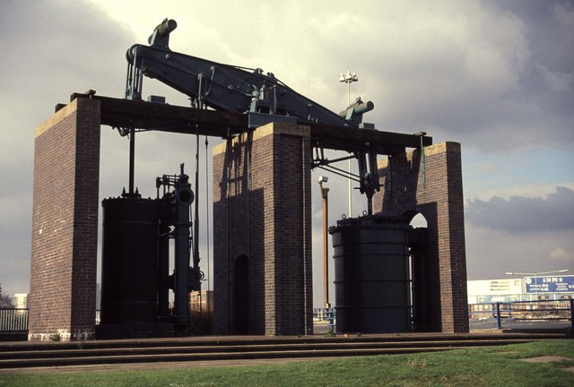
An 1817 beam blowing engine by Boulton & Watt, formerly used at the Netherton ironworks of M W Grazebrook, now decorates Dartmouth Circus, a traffic island at the start of the A38(M) motorway in Birmingham (see picture above, location: ).
References
References
- {{Book-Hills-Power from Steam
- [[#Hawkins, New Catechism of the Steam Engine. Hawkins, New Catechism of the Steam Engine]], p.225, p.172
This article was imported from Wikipedia and is available under the Creative Commons Attribution-ShareAlike 4.0 License. Content has been adapted to SurfDoc format. Original contributors can be found on the article history page.
Ask Mako anything about Blowing engine — get instant answers, deeper analysis, and related topics.
Research with MakoFree with your Surf account
Create a free account to save articles, ask Mako questions, and organize your research.
Sign up freeThis content may have been generated or modified by AI. CloudSurf Software LLC is not responsible for the accuracy, completeness, or reliability of AI-generated content. Always verify important information from primary sources.
Report