From Surf Wiki (app.surf) — the open knowledge base
Apollo TV camera
Portable TV camera suitable for space operations
Portable TV camera suitable for space operations
The Apollo program used several television cameras in its space missions in the late 1960s and 1970s; some of these Apollo TV cameras were also used on the later Skylab and Apollo–Soyuz Test Project missions. These cameras varied in design, with image quality improving significantly with each successive model. Two companies made these various camera systems: RCA and Westinghouse. Originally, these slow-scan television (SSTV) cameras, running at 10 frames per second (fps), produced only black-and-white pictures and first flew on the Apollo 7 mission in October 1968. A color camera – using a field-sequential color system – flew on the Apollo 10 mission in May 1969, and every mission after that. The color camera ran at the North American standard 30 fps. The cameras all used image pickup tubes that were initially fragile, as one was irreparably damaged during the live broadcast of the Apollo 12 mission's first moonwalk. Starting with the Apollo 15 mission, a more robust, damage-resistant camera was used on the lunar surface. All of these cameras required signal processing back on Earth to make the frame rate and color encoding compatible with analog broadcast television standards.
Starting with Apollo 7, a camera was carried on every Apollo command module (CM) except Apollo 9. For each lunar landing mission, a camera was also placed inside the Apollo Lunar Module (LM) descent stage's modularized equipment stowage assembly (MESA). Positioning the camera in the MESA made it possible to telecast the astronauts' first steps as they climbed down the LM's ladder at the start of a mission's first moonwalk/EVA. Afterwards, the camera would be detached from its mount in the MESA, mounted on a tripod and carried away from the LM to show the EVA's progress; or, mounted on a Lunar Roving Vehicle (LRV), where it could be remotely controlled from Mission Control on Earth.
RCA command module TV camera
Development
NASA decided on initial specifications for TV on the Apollo command module (CM) in 1962. Both analog and digital transmission techniques were studied, but the early digital systems still used more bandwidth than an analog approach: 20 MHz for the digital system, compared to 500 kHz for the analog system. The video standard for the Block I CM meant that the analog video standard for early Apollo missions was set as follows: monochrome signal, with 320 active scan lines, and progressively scanned at 10 frames per second (fps). RCA was given the contract to manufacture such a camera. It was understood at the time that motion fidelity from such a slow-scan television system (SSTV) would be less than standard commercial television systems, but deemed sufficient considering that astronauts would not be moving quickly in orbit, or even on the Lunar surface.
Video signal processing
Since the camera's scan rate was much lower than the approximately 30 fps for NTSC video, the television standard used in North America at the time, a real-time scan conversion was needed to be able to show its images on a regular TV set. NASA selected a scan converter manufactured by RCA to convert the black-and-white SSTV signals from the Apollo 7, 8, 9, and 11 missions.
When the Apollo TV camera transmitted its images, the ground stations received its raw unconverted SSTV signal and split it into two branches. One signal branch was sent unprocessed to a fourteen-track analog data tape recorder where it was recorded onto fourteen-inch diameter reels of one-inch-wide analog magnetic data tapes at 3.04 meters per second. The other raw SSTV signal branch was sent to the RCA scan converter where it would be processed into an NTSC broadcast television signal.
The conversion process started when the signal was sent to the RCA converter's high-quality 10-inch video monitor where a conventional RCA TK-22 television camera – using the NTSC broadcast standard of 525 scanned lines interlaced at 30 fps – merely re-photographed its screen. The monitor had persistent phosphors, that acted as a primitive framebuffer. An analog disk recorder, based on the Ampex HS-100 model, was used to record the first field from the camera. It then fed that field, and an appropriately time-delayed copy of the first field, to the NTSC field interlace switch (encoder). The combined original and copied fields created the first full 525-line interlaced frame and the signal was then sent to Houston. It repeated this sequence five more times, until the system imaged the next SSTV frame. It then repeated the whole process with each new frame downloaded from space in real time. In this way, the chain produced the extra 20 frames per second needed to produce flicker-free images to the world's television broadcasters.
This live conversion was crude compared to early 21st-century electronic digital conversion techniques. Image degradation was unavoidable with this system as the monitor and camera's optical limitations significantly lowered the original SSTV signal's contrast, brightness and resolution. The video seen on home television sets was further degraded by the very long and noisy analog transmission path. The converted signal was sent by satellite from the receiving ground stations to Houston, Texas. Then the network pool feed was sent by microwave relay to New York, where it was broadcast live to the United States and the world.
Operational history

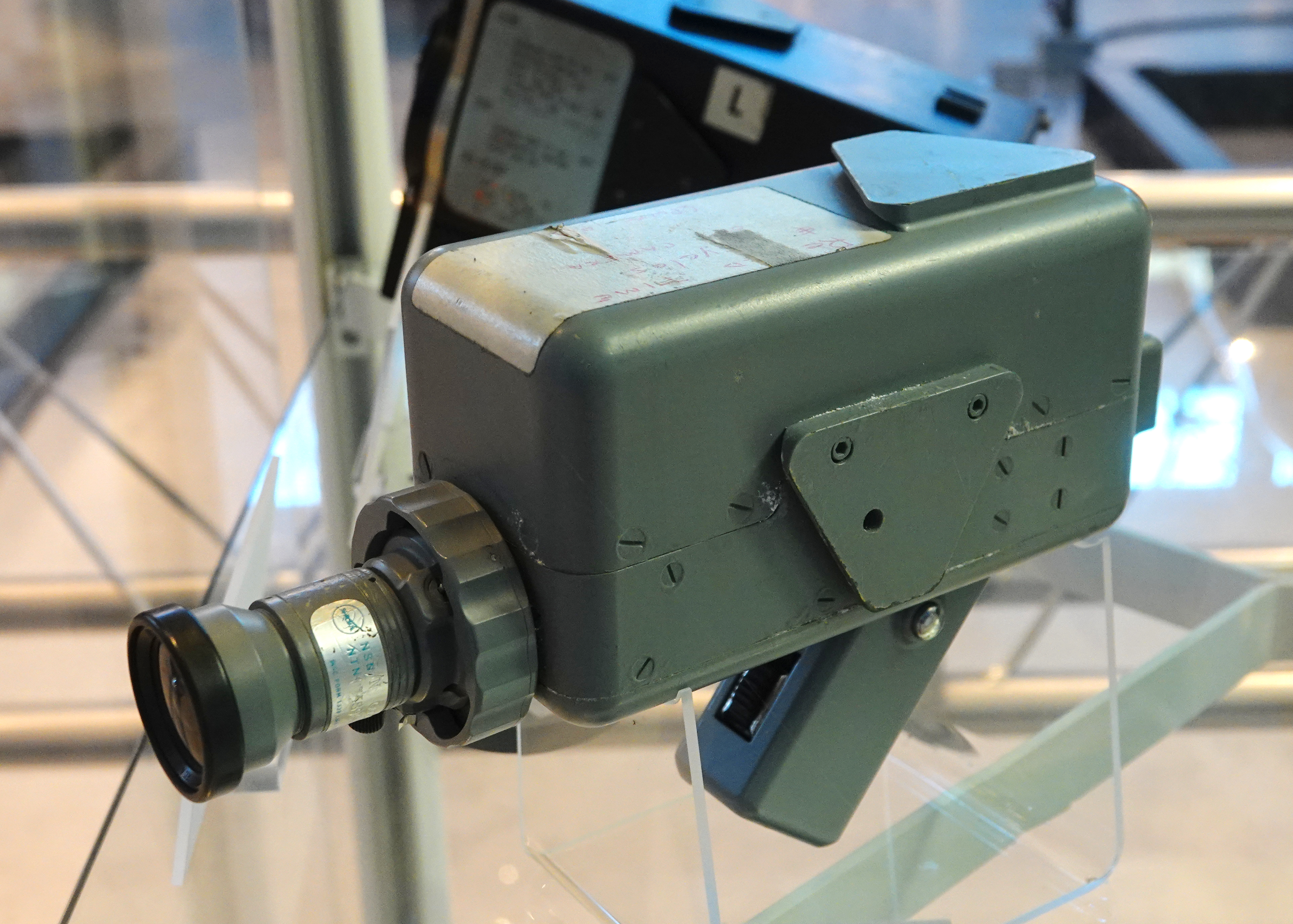
Apollo 7 and Apollo 8 used an RCA slow-scan, black-and-white camera. On Apollo 7, the camera could be fitted with either a wide angle 160-degree lens, or a telephoto lens with a 9-degree angle of view. The camera did not have a viewfinder or a monitor, so astronauts needed help from Mission Control when aiming the camera in telephoto mode.
Specifications
The camera used interchangeable lenses, including a wide-angle lens with a 160-degree field-of-view, and a 100 mm telephoto lens.
Camera
| Lens mount type | Bayonet |
|---|
Westinghouse Apollo lunar television camera
Development


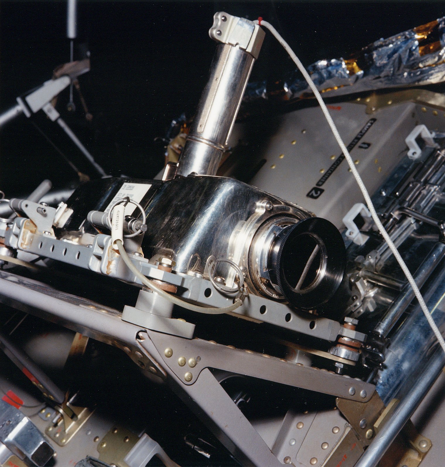
In October 1964, NASA awarded Westinghouse the contract for the lunar TV camera. Stan Lebar, the program manager for the Apollo lunar TV camera, headed the team at Westinghouse that developed the camera that brought pictures from the Moon's surface.
The camera had to be designed to survive extreme temperature differences on the lunar surface, ranging from 121 C in daylight to -157 C in the shade. Another requirement was to be able to keep the power to approximately 7 watts, and fit the signal into the narrow bandwidth on the LM's S-band antenna, which was much smaller and less powerful than the service module's antenna.
Operational history

.jpg)
The camera was first tested in space during the Apollo 9 mission in March 1969. The camera was stowed in the LM, and it used the LM's communications systems to evaluate their performance before lunar operations began. This meant that the CM did not carry a video camera for this mission. It was next used on Apollo 11, carried in the LM's descent stage, in the quad 4 Modularized Equipment Stowage Assembly (MESA). It was from the MESA where it captured humanity's first step on another celestial body on 21 July 1969. Apollo 11 would be the first and last time the camera was used on the Lunar surface; however, it flew as a backup camera on the Apollo missions from Apollo 13 to Apollo 16, in case the color cameras suffered a similar fate as the Apollo 12 camera.
Specifications
The camera's dimensions were 269 x in size, and weighed 3.29 kg. It consumed 6.50 watts of power. Its bayonet lens mount allowed for quick changes for the two interchangeable lenses used on Apollo 11: a wide-angle and a lunar day lens.
Camera
| Lens mount type | Bayonet |
|---|
Lenses
| Lens | Westinghouse Part No. | Supplier | Field-of-View | Zoom Ratio | Aperture | Light transmission | Weight | Dimensions | Lens mount type |
|---|---|---|---|---|---|---|---|---|---|
| Wide Angle Lens | 578R159-1 | Fairchild | 80 degrees | N/A | F 4 | T 4.8 | 100 g | 33 mm long | Bayonet |
| 100 mm Lens | 578R159-2 | Fairchild | 9.3 degrees | N/A | F 4 | T 60 | 417 g | 126 mm long | Bayonet |
| Lunar Day Lens | 578R159-3 | Fairchild | 35 degrees | N/A | F 4 | T 60 | 100 g | 39 mm long | Bayonet |
| Lunar Night Lens | 578R159-4 | Fairchild | 35 degrees | N/A | F 1 | T 1.15 | 200 g | 53 mm long | Bayonet |
Image:Apollo11Honeysuckle.jpg |Photo of the high-quality SSTV image received from Apollo 11 at Honeysuckle Creek Tracking Station Image:Apollo11A.jpg |Photo of the high-quality SSTV image before the scan conversion Image:Apollo11C.jpg |Photo of the high-quality SSTV image before the scan conversion Image:Apollo 11 TV Camera.JPG |Westinghouse camera on the Lunar surface during Apollo 11
Westinghouse lunar color camera
Choosing a color process

Color broadcast studio television cameras in the 1960s, such as the RCA TK-41, were large, heavy and high in energy consumption. They used three imaging tubes to generate red, green and blue (RGB) video signals which were combined to produce a composite color picture. These cameras required complex optics to keep the tubes aligned. Since temperature variations and vibration would easily put a three-tube system out of alignment, a more robust system was needed for lunar surface operations.
In the 1940s, CBS Laboratories invented an early color system that utilized a wheel, containing six color filters, rotated in front of a single video camera tube to generate the RGB signal. Called a field-sequential color system, it used interlaced video, with sequentially alternating color video fields to produce one complete video frame. That meant that the first field would be red, the second blue, and the third field green – matching the color filters on the wheel. This system was both simpler and more reliable than a standard three-tube color camera, and more power-efficient.
The camera
Lebar and his Westinghouse team wanted to add color to their camera as early as 1967, and they knew that the CBS system would likely be the best system to study. The Westinghouse lunar color camera used a modified version of CBS's field-sequential color system. A color wheel, with six filter segments, was placed behind the lens mount. It rotated at 9.99 revolutions per second, producing a scan rate of 59.94 fields per second, the same as NTSC video. Synchronization between the color wheel and pickup tube's scan rate was provided by a magnet on the wheel, which controlled the sync pulse generator that governed the tube's timing.
The color camera used the same SEC video imaging tube as the monochrome lunar camera flown on Apollo 9. The camera was larger, measuring 17 in long, including the new zoom lens. The zoom lens had a focal length variable from 25 mm to 150 mm, i.e. a zoom ratio of 6:1. At its widest angle, it had a 43-degree field of view, while in its extreme telephoto mode, it had a 7-degree field of view. The aperture ranged from F4 to F44, with a T5 light transmittance rating.
Color decoding and signal processing
Signal processing was needed at the Earth receiving ground stations to compensate for the Doppler effect, caused by the spacecraft moving away from or towards the Earth. The Doppler Effect would distort color, so a system that employed two videotape recorders (VTRs), with a tape-loop delay to compensate for the effect, was developed. The cleaned signal was then transmitted to Houston in NTSC-compatible black and white.
Unlike the CBS system that required a special mechanical receiver on a TV set to decode the color, the signal was decoded in Houston's Mission Control Center. This video processing occurred in real time. The decoder separately recorded each red, blue and green field onto an analog magnetic disk recorder. Acting as a framebuffer, it then sent the coordinated color information to an encoder to produce a NTSC color video signal and then released to the broadcast pool feed. Once the color was decoded, scan conversion was not necessary, because the color camera ran at the same 60-fields-per-second video interlace rate as the NTSC standard.
Operational history
It was first used on the Apollo 10 mission. The camera used the command module's extra S-band channel and large S-band antenna to accommodate the camera's larger bandwidth. It was only used in the lunar module when it was docked to the command module. Unlike the earlier cameras, it contained a portable video monitor that could be either directly attached to the camera or float separately. Combined with the new zoom lens, it allowed the astronauts to have better precision with their framing.
Apollo 12 was the first mission to use the color camera on the lunar surface. About 42 minutes into telecasting the first EVA, astronaut Alan Bean inadvertently pointed the camera at the Sun while preparing to mount it on the tripod. The Sun's extreme brightness burned out the video pickup tube, rendering the camera useless. When the camera was returned to Earth, it was shipped to Westinghouse, and they were able to get an image on the section of the tube that wasn't damaged. Procedures were re-written in order to prevent such damage in the future, including the addition of a lens cap to protect the tube when the camera was repositioned off the MESA.

The color camera successfully covered the lunar operations during the Apollo 14 mission in 1971. Image quality issues appeared due to the camera's automatic gain control (AGC) having problems getting the proper exposure when the astronauts were in high contrast light situations, and caused the white spacesuits to be overexposed or "bloom". The camera did not have a gamma correction circuit. This resulted in the image's mid-tones losing detail.
After Apollo 14, it was only used in the command module, as the new RCA-built camera replaced it for lunar surface operations. The Westinghouse color camera continued to be used throughout the 1970s on all three Skylab missions and the Apollo–Soyuz Test Project.
The 1969–1970 Emmy Awards for Outstanding Achievement in Technical/Engineering Development were awarded to NASA for the conceptual aspects of the color Apollo television camera and to Westinghouse Electric Corporation for the development of the camera.
Specifications
Camera
| Lens mount type | C mount |
|---|
Lens
| Lens mount type | C mount ANSI 1000-32NS-2A thread |
|---|
Image:Apollo10S69-33995.jpg|Apollo 10 TV image of Earth Image:Apollo11tv.jpg|Apollo 11 TV image Image:Apollo 12 TV Camera.jpg|Westinghouse color camera on the lunar surface during Apollo 12 Image:Apollo 14 Camera.JPG|Edgar Mitchell with the Apollo 14 camera
RCA J-series ground-commanded television assembly (GCTA)
Due to Apollo 12's camera failure, a new contract was awarded to the RCA Astro Electronics facility in East Windsor, New Jersey. The design team was headed by Robert G. Horner. The RCA system used a new, more sensitive and durable TV camera tube, the newly developed Silicon intensifier target (SIT) pickup tube. The improved image quality was obvious to the public with the RCA camera's better tonal detail in the midrange, and the lack of the blooming that was apparent in the previous missions.
The system was composed of the color television camera (CTV) and the television control unit (TCU). These were connected to the lunar communications relay unit (LCRU) when mounted on the Lunar Roving Vehicle (LRV). Like the Westinghouse color camera, it used the field-sequential color system, and used the same ground-station signal processing and color decoding techniques to produce a broadcast NTSC color video signal.
On Apollo 15 the camera produced live images from the LM's MESA, just as the previous missions did. It was repositioned from the MESA onto a tripod, where it photographed the Lunar Rover Vehicle (LRV) being deployed. Once the LRV was fully deployed, the camera was mounted there and controlled by commands from the ground to tilt, pan, and zoom in and out. This was the last mission to have live video of the mission's first steps via the MESA, as on the following flights it was stowed with the LRV.
| Lens | 6× zoom, F/2.2 to F/22 |
|---|
File:Robert.G.Horner in pr Photo demonstrating RCA's new Apollo camera with Silicon Intensifier Tube (SIT).jpg|Robert.G.Horner in 1970 pr photo demonstrating RCA's Apollo camera with Silicon Intensifier Tube (SIT) File:GCTA transmission from the LRV (small).jpg|GCTA transmission from the LRV File:Apollo 15 Television Camera.JPG|Apollo 15 television camera and high-gain antenna File:Apollo 16 TV Camera.jpg|Apollo 16 television camera. Notice the sunshade attached to the top of the lens, a feature first used on Apollo 16.
Usage
Cameras used, CM = command module, LM = lunar module
- Apollo 7: RCA B&W SSTV (CM)
- Apollo 8: RCA B&W SSTV (CM)
- Apollo 9: Westinghouse B&W (LM)
- Apollo 10: Westinghouse color (CM)
- Apollo 11: Westinghouse color (CM), Westinghouse B&W (LM)
- Apollo 12: Westinghouse color (CM & LM)
- Apollo 13: Westinghouse color (CM & LM), Westinghouse B&W was a backup for LM (not used)
- Apollo 14: Westinghouse color (CM & LM), Westinghouse B&W was a backup for LM (not used)
- Apollo 15: Westinghouse color (CM), RCA GCTA (LM), Westinghouse B&W was a backup for LM (not used)
- Apollo 16: Westinghouse color (CM), RCA GCTA (LM), Westinghouse B&W was a backup for LM (not used)
- Apollo 17: Westinghouse color (CM), RCA GCTA (LM)
Notes
Citations
References
- {{cite news
| access-date = 17 May 2025 | url-access = subscription
-
{{Citation |editor-last=Jones |editor-first=Eric M. |editor2-last=Glover |editor2-first=Ken |publication-date=1996–2013 |chapter-url=http://www.hq.nasa.gov/alsj/LC-SOW.pdf |access-date=2013-10-20 |archive-url=https://web.archive.org/web/20041117090603/http://www.hq.nasa.gov/alsj/LC-SOW.pdf |archive-date=17 November 2004 |url-status=live
-
{{cite book
-
{{Citation |access-date=2019-11-12
-
{{Citation |editor-last=Jones |editor-first=Eric M. |editor2-last=Glover |editor2-first=Ken |publication-date=1996–2013 |chapter-url=http://www.hq.nasa.gov/alsj/Electronics-670306.pdf |access-date=2013-10-20 |archive-url=https://web.archive.org/web/20060808205026/http://www.hq.nasa.gov/alsj/Electronics-670306.pdf |archive-date=8 August 2006 |url-status=live
-
{{Citation |editor-last=Jones |editor-first=Eric M. |editor2-last=Glover |editor2-first=Ken |publication-date=1996–2013 |chapter-url=http://www.hq.nasa.gov/alsj/WEC-Lunar-Camera-Manual.pdf |access-date=2013-10-20 |archive-url=https://web.archive.org/web/20060926082408/http://www.hq.nasa.gov/alsj/WEC-Lunar-Camera-Manual.pdf |archive-date=26 September 2006 |url-status=live
-
{{cite news
-
{{Citation | editor-last = Jones | editor-first = Eric M. | editor2-last = Glover | editor2-first = Ken | publication-date = 1996–2013 | chapter-url = https://ntrs.nasa.gov/archive/nasa/casi.ntrs.nasa.gov/19790073158_1979073158.pdf
-
{{cite news |access-date=2013-10-18 |archive-url=https://web.archive.org/web/20131019101731/http://www.tvtechnology.com/feature-box/0124/tvs-longest-remote/202657 |archive-date=19 October 2013 |url-status=dead
-
{{cite news |access-date=2013-10-18 |archive-url=https://web.archive.org/web/20131019101734/http://www.tvtechnology.com/feature-box/0124/equipping-apollo-for-color-television/202793 |archive-date=19 October 2013 |url-status=dead
-
{{cite news |access-date=2013-10-18 |archive-url=https://web.archive.org/web/20131019101737/http://www.tvtechnology.com/feature-box/0124/search-for-missing-recordings-ends/202982 |archive-date=19 October 2013 |url-status=dead
-
{{cite news | access-date = 2013-10-15
-
{{Citation |editor-last=Jones |editor-first=Eric M. |editor2-last=Glover |editor2-first=Ken |publication-date=1996–2013 |chapter-url=http://www.hq.nasa.gov/alsj/TM-X55492.pdf |access-date=2013-10-20 |archive-url=https://web.archive.org/web/20060830211719/http://www.hq.nasa.gov/alsj/TM-X55492.pdf |archive-date=30 August 2006 |url-status=live
-
{{Cite web |access-date=2024-05-30 |archive-url=https://web.archive.org/web/20100519150125/http://ntrs.nasa.gov/archive/nasa/casi.ntrs.nasa.gov/19730010465_1973010465.pdf |archive-date=19 May 2010 |url-status=dead
-
{{cite journal |access-date=2013-10-17 |archive-url=https://web.archive.org/web/20070831164351/http://www.parkes.atnf.csiro.au/news_events/apollo11/pasa/on_eagles_wings.pdf |archive-date=31 August 2007 |url-status=live |doi-access=free
-
{{cite web |access-date=2013-10-15 |archive-url=https://web.archive.org/web/20060721092756/http://www.honeysucklecreek.net/Apollo_11/tapes/Search_for_SSTV_Tapes.pdf |archive-date=21 July 2006 |url-status=live
-
{{cite book
-
{{cite news |access-date=2013-10-16 |archive-url=https://web.archive.org/web/20120723123929/http://www.theatlantic.com/video/archive/2012/07/1-small-step-for-a-cam-how-astronauts-shot-video-of-the-moon-landing/260122/ |archive-date=23 July 2012 |url-status=live
-
{{Citation |access-date=2013-10-19 |archive-url=https://web.archive.org/web/20041117090707/http://www.hq.nasa.gov/alsj/WEC-ColorTV-Manual.pdf |archive-date=17 November 2004 |url-status=live
-
{{cite news
-
{{cite book | url-access = registration
-
{{cite web |access-date=2011-12-09 |archive-url=https://web.archive.org/web/20020611221953/http://www.clavius.org/tvqual.html |archive-date=11 June 2002 |url-status=live
-
{{Citation | editor-last = Jones | editor-first = Eric M. | editor2-last = Glover | editor2-first = Ken | publication-date = 1996–2013 | chapter-url = http://www.hq.nasa.gov/alsj/ApolloTV-Acrobat7.pdf
This article was imported from Wikipedia and is available under the Creative Commons Attribution-ShareAlike 4.0 License. Content has been adapted to SurfDoc format. Original contributors can be found on the article history page.
Ask Mako anything about Apollo TV camera — get instant answers, deeper analysis, and related topics.
Research with MakoFree with your Surf account
Create a free account to save articles, ask Mako questions, and organize your research.
Sign up freeThis content may have been generated or modified by AI. CloudSurf Software LLC is not responsible for the accuracy, completeness, or reliability of AI-generated content. Always verify important information from primary sources.
Report